Dissolving apparatus

A dissolving device and solution technology, applied in the direction of dissolution, dissolution, transportation and packaging, etc., can solve the problem of inability to dissolve gas into liquid, and achieve the effect of increasing solubility

Inactive Publication Date: 2011-02-16
康源太
View PDF8 Cites 4 Cited by
  • Summary
  • Abstract
  • Description
  • Claims
  • Application Information

AI Technical Summary

Problems solved by technology

Therefore, this conventional device has the disadvantage of not being able to effectively dissolve the gas into the liquid

Method used


Image

  • Dissolving apparatus
  • Dissolving apparatus
  • Dissolving apparatus

Examples


no. 1 example

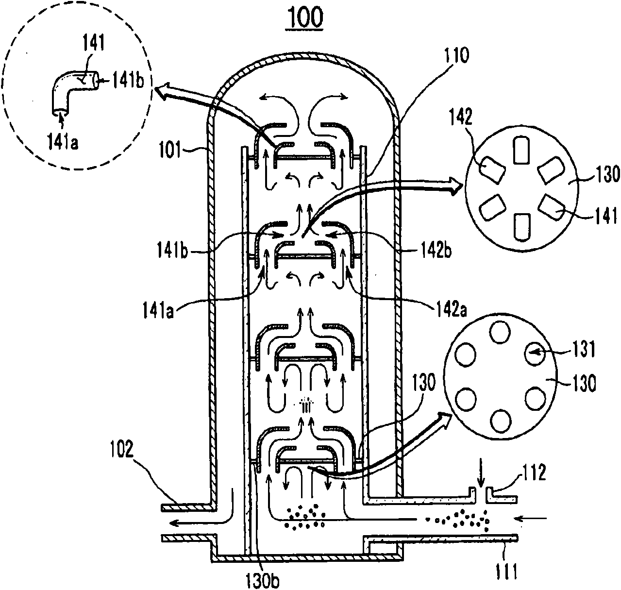
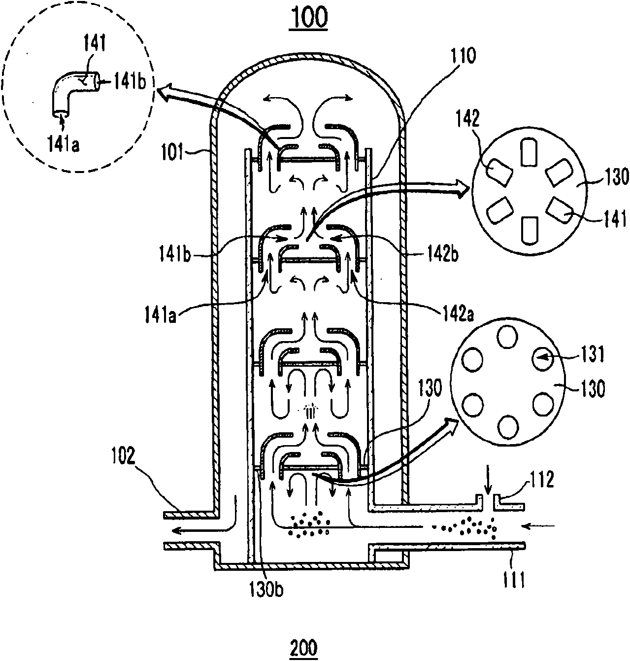
[0012] figure 1 is a cross-sectional view of the dissolving device 100 according to the first embodiment of the present invention, showing the circulation of the first fluid and the second fluid.

[0013] Such as figure 1 As shown, the dissolution device 100 according to the present invention includes a wear-resistant tank 101 , a first supply pipe 111 , a second supply pipe 112 , a vortex guide shell 110 , a plate 130 , and vortex guide pipes 141 and 142 . The dissolving device 100 forms a solution by dissolving the second fluid in the first fluid. The first fluid is a liquid, such as water, and the second fluid is a gas or liquid with properties different from those of the first fluid. In the following description, the first fluid is referred to as a first liquid, and the second fluid is referred to as a second liquid or gas for convenience.

[0014] The wear tank 101 surrounds the vortex guide shell 110 and has an outlet 102 for draining the solution on one side of the w...

no. 2 example

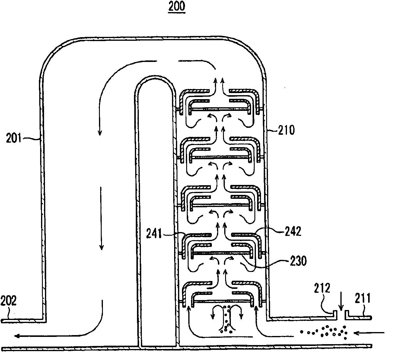
[0030] figure 2 is a cross-sectional view of a dissolving device 200 according to a second embodiment of the present invention, showing the circulation of the first fluid and gas. The circulation of the first liquid and the second liquid is the same as that of the first liquid and the gas.

[0031] In this embodiment, the description of the structure of the vortex guide shell 210, the structure and position of the plate 230 and the vortex guide pipes 241 and 242, the positions of the first supply pipe 211 and the second supply pipe 212, the flow direction of the liquid, and The flow direction of gas is omitted since the above structure has the same function as that of the first embodiment.

[0032] Only the structure of the wear-resistant tank 201 and the connection between the wear-resistant tank 201 and the eddy current guide shell 210 will be described below, wherein the wear-resistant tank 201 and the eddy current guide shell 210 are different from the wear-resistant tank ...


PUM


Abstract

The present invention relates to a dissolving apparatus for producing a dissolved solution by dissolving a primary fluid into a secondary fluid. The dissolving apparatus comprises: a primary supply pipe for supplying the primary fluid, a secondary supply pipe for supplying the secondary fluid, a vortex induction housing which is connected to the primary and secondary supply pipes and has an open top and a closed bottom to let the primary and secondary fluids move upward, a plate which closes the inside of the vortex induction housing and has multiple openings, vortex induction pipes which are installed in the openings of the plate to move the primary and secondary fluids to the top of the vortex induction housing, and a retention tank which has an outlet on one side to discharge the dissolved solution in which the primary and secondary fluids are dissolved and surrounds the vortex induction housing to guide the dissolved solution from the open top of the vortex induction housing to the outlet. The vortex induction pipes are arranged in pairs so that outlets for the primary and secondary fluids face each other.

Description

technical field [0001] The present invention relates to a dissolving device, and more particularly to a dissolving device having a plurality of vortex guide tubes and plates, thereby increasing the solubility of a second fluid to a first fluid, so as to dissolve the two fluids. Background technique [0002] Generally, carbonated water is made by using a specific container that can hold water to a predetermined depth, and the gas injection nozzle has a seal that seals the inlet of the specific container. After water is injected into the container and the inlet of the container is sealed by a seal, CO 2 Injected into the container to convert CO 2 Dissolve in water to make carbonated water. [0003] However, since this conventional apparatus for making carbonated water is formed by directly injecting gas into the liquid through the gas injection nozzle, the contact area between the gas and the liquid is limited to the gas injection area. Therefore, this conventional device h...

Claims


Application Information

Patent Timeline
IPC IPC(8): B01F1/00
CPCB01F5/0644B01F3/04787B01F23/236B01F25/4323C02F1/68B01F21/00B01F23/20B01F25/40
Inventor 康源太
Owner 康源太
Why Eureka
Try Eureka