Check patentability & draft patents in minutes with Patsnap Eureka AI!

Gear device and power transmission apparatus

A power transmission device and gear device technology, which is applied in the direction of gear transmission device, transmission device, gear vibration/noise attenuation, etc., can solve the problems of weight increase and vehicle manufacturing cost increase, and achieve the goal of reducing vibration and noise and suppressing resonance Effect

Inactive Publication Date: 2011-02-16
TOYOTA JIDOSHA KK
View PDF7 Cites 4 Cited by
  • Summary
  • Abstract
  • Description
  • Claims
  • Application Information

AI Technical Summary

Problems solved by technology

However, since this solution will lead to an increase in the manufacturing cost and weight of the vehicle, it is difficult to adopt it in most cases.

Method used


Image

  • Gear device and power transmission apparatus
  • Gear device and power transmission apparatus
  • Gear device and power transmission apparatus

Examples


Embodiment

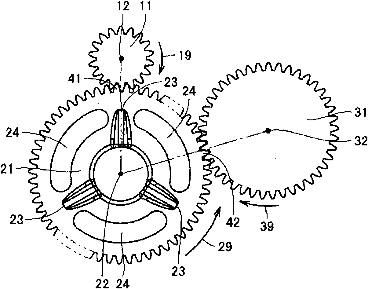
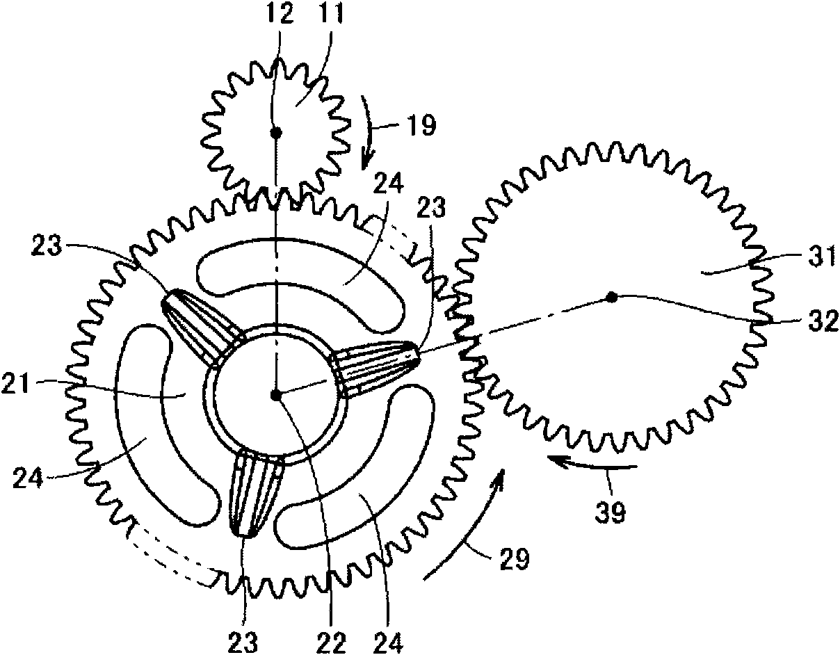
[0067] Next, examples of the present invention will be described. A simulation experiment to calculate the vibration of the entire gear device was performed on a gear device having a three-shaft structure including the second gear having the through hole described in the above-mentioned embodiment. In addition, as a first comparative example, the vibration amount of the entire gear device was calculated for a gear device including a second gear with no through hole formed therein. In addition, as a second comparative example, although the second gear is provided with a through hole, the first gear and the third gear are both arranged in the direction extending from the rotation center of the second gear toward the connecting portion or the through hole. For gear units, the amount of vibration is calculated for the entire gear unit.

[0068] Figure 5A ~ Figure 5C It is a figure which shows the vibration of the gear apparatus of the 1st comparative example. Figure 5AThe vib...


PUM


Abstract

A gear device which vibrates less and emits less noise is provided. The gear device has a first gear (11) provided on a first shaft, a second gear (21) provided on a second shaft and meshing with the first gear (11), and a third gear (31) provided on a third shaft and meshing with the second gear (21). The second gear (21) has formed therein through-holes (24) extending in the circumferential direction about the rotation axis of the second gear, and this changes the circumferential rigidity of the second gear. The first and third gears (11, 31) are arranged such that the rigidity of the second gear (21) at certain time at the point (41) of meshing between the first and second gears (11, 21) and the rigidity of the second gear (21) at the point (42) of meshing between the second and the third gears (21, 31) are different from each other.

Description

technical field [0001] The invention relates to a gear device and a power transmission device, in particular to a gear device with a three-shaft structure and a power transmission device with the gear device. Background technique [0002] Conventionally, various techniques have been proposed regarding the gear device. For example, in Japanese Unexamined Patent Publication No. 2005-69401 (Patent Document 1), it is proposed to form a through hole in the circumferential direction of the rotating shaft of one gear on a pair of gears with a two-shaft structure, so that the rigidity of the meshing occurs. Changes, thereby suppressing the resonance technology. [0003] In Japanese Unexamined Patent Publication No. 7-35202 (Patent Document 2), a technique of increasing the support rigidity of a gear shaft according to the direction of vibration is proposed. In Japanese Patent Application Laid-Open No. 2-8537 (Patent Document 3), it is proposed that in a three-axis gear mechanism, ...

Claims


Application Information

Patent Timeline
IPC IPC(8): F16H1/20F16H55/17
CPCF16H55/14F16H3/727F16H57/0006F16H1/20Y10T74/19633
Inventor 清水隆
Owner TOYOTA JIDOSHA KK
Features
  • R&D
  • Intellectual Property
  • Life Sciences
  • Materials
  • Tech Scout
  • Unparalleled Data Quality
  • Higher Quality Content
  • 60% Fewer Hallucinations
Learn More