Metallurgical liquid tank

A liquid tank and tank mouth technology, applied in the field of metallurgical liquid tanks, can solve problems such as poor thermal insulation effect, and achieve the effect of convenient overhaul

Active Publication Date: 2012-02-29
冀南钢铁集团有限公司
View PDF0 Cites 0 Cited by
  • Summary
  • Abstract
  • Description
  • Claims
  • Application Information

AI Technical Summary

Problems solved by technology

However, if the insulation layer of a metallurgical liquid tank is insulated with ordinary insulation materials, its insulation effect is relatively poor.

Method used


Image

  • Metallurgical liquid tank
  • Metallurgical liquid tank
  • Metallurgical liquid tank

Examples


Embodiment Construction

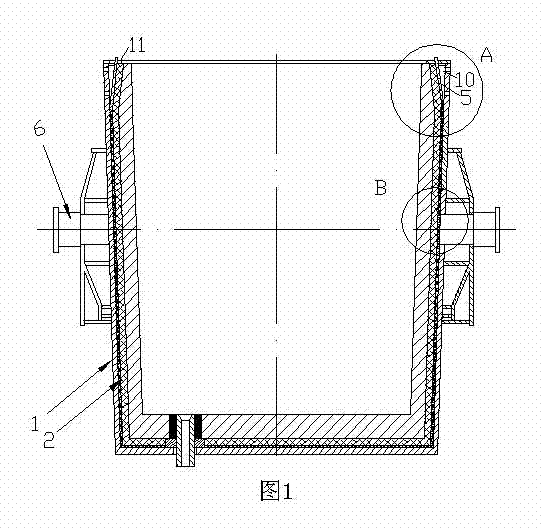
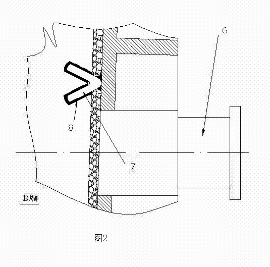
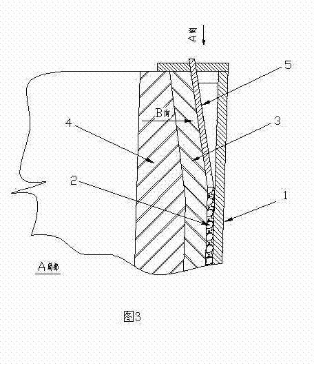
[0016] As shown in the figure, a metallurgical liquid tank includes a tank shell 1, a trunnion 6, a tank mouth flange 11, an insulation layer 2, a permanent layer 3, a refractory working layer 4 and a permanent layer material anchor nail 7, which is characterized in that : the inner wall of the tank mouth of the tank shell 1 is provided with a plurality of tank mouth flange anchor plates 5, and the tank mouth flange 11 has an anchor plate passage hole corresponding to and matched with the tank mouth flange anchor plate 5, and anchoring The plate 5 is higher than the upper surface of the tank mouth flange 11, and the tank mouth flange 11 is fixed on the upper port of the tank mouth by discontinuous welding with each tank mouth flange anchor plate 5, and the tank mouth flange is anchored The plate 5 gradually moves away from the inner surface of the tank shell 1 upwards from the connection with the inner surface of the tank shell 1 , and a reinforcing rib 10 is arranged between t...


PUM


Abstract

The invention discloses a metallurgical liquid tank, which comprises a tank shell, a lug shaft, a tank port flange, a heat insulation layer, a permanent layer, a refractory material working layer and a permanent material anchoring nail, wherein the inner wall of the tank port of the tank shell is provided with a plurality of tank port flange anchoring plates; the tank port flange is provided withanchoring plate through holes corresponding to and matched with the tank port flange anchoring plates; the anchoring plates are higher than the upper surface of the tank port flange; and the tank port flange is fixed on the upper port of the tank port by discontinuous welding with each tank port flange anchoring plate, the tank port flange anchoring plates are gradually upward away from the surface of the tank shell from a joint to the surface of the tank shell, stiffeners are arranged between the tank port plange anchoring plates and the inner surface of the tank shell. The metallurgical liquid tank is convenient to overhaul and as firm as the tank port flange is discontinuously welded, and the permanent layer and the working layer are not easily separated from the tank shell during buckling the tank.

Description

technical field [0001] The invention relates to a metallurgical liquid tank, in particular to a metallurgical liquid tank in which the permanent layer and the working layer are not easy to separate from the tank shell when the slag is buckled. Background technique [0002] At present, the tank mouth flange of the metallurgical liquid tank is continuously welded and fixed, and the tank flange must be cut off every time the metallurgical liquid tank is overhauled. After the masonry is completed, re-welding the cut tank mouth flange is time-consuming and laborious, and the work efficiency is low. If the tank mouth flange and the tank mouth are discontinuously welded, especially when the composite reflective heat insulation board is used as the insulation layer, since the composite reflective heat insulation board is characterized by a multi-layer structure, the sliding surface is rich so that the permanent layer and the liquid tank shell The loss of adhesion between the tanks...

Claims


Application Information

Patent Timeline
Patent Type & Authority Patents(China)
IPC IPC(8): C21B3/10
Inventor 王金星赵欣赵一萍王爱国刘炳钊李萍边仁杰王新召
Owner 冀南钢铁集团有限公司
Why Eureka
Try Eureka