Path calculation method, system and node equipment

A technology of path calculation and node equipment, which is applied in the field of transmission network, can solve the problems of unfavorable network stability such as simplification of PCE side processing flow, achieve the effect of simplifying the synchronization processing flow of resource allocation information and improving reliability

Inactive Publication Date: 2011-03-09
ZTE CORP
View PDF2 Cites 22 Cited by
  • Summary
  • Abstract
  • Description
  • Claims
  • Application Information

AI Technical Summary

Problems solved by technology

At this time, PCEP messages will "broadcast" synchronization resource allocation information. If the amount of PCEP NOTIFY messages exc

Method used


Image

  • Path calculation method, system and node equipment
  • Path calculation method, system and node equipment
  • Path calculation method, system and node equipment

Examples


Embodiment 1

[0054] This embodiment provides a path calculation system, which at least includes node devices and several PCE servers.

[0055] The node device is mainly used to receive the path computation request, and to select the active PCE server according to the set selection strategy from the path computation unit PCE server that can execute the received path computation request in the path computation domain, The received path calculation request is sent to the active PCE server, wherein, the node device requests the active PCE server for path calculation and resource allocation, IV (Impairment Validation), etc. through the PCEP protocol;

[0056] The node equipment can be further divided into a transceiver unit and a PCE server selection unit;

[0057] The transceiver unit is configured to receive a path calculation request, and send the path calculation request to the active PCE server selected by the path calculation unit PCE server, so as to perform path calculation and resource...

Embodiment 2

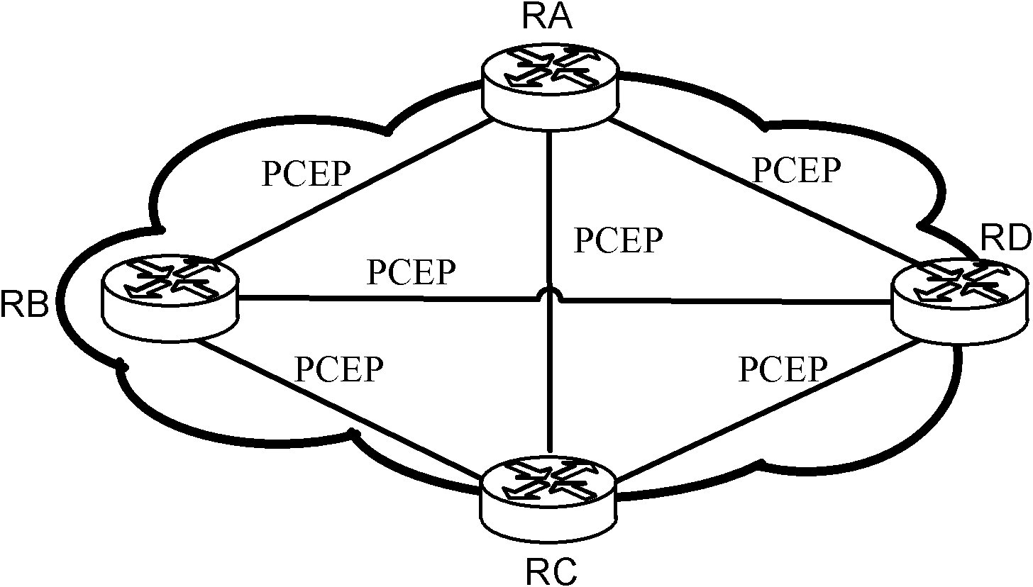
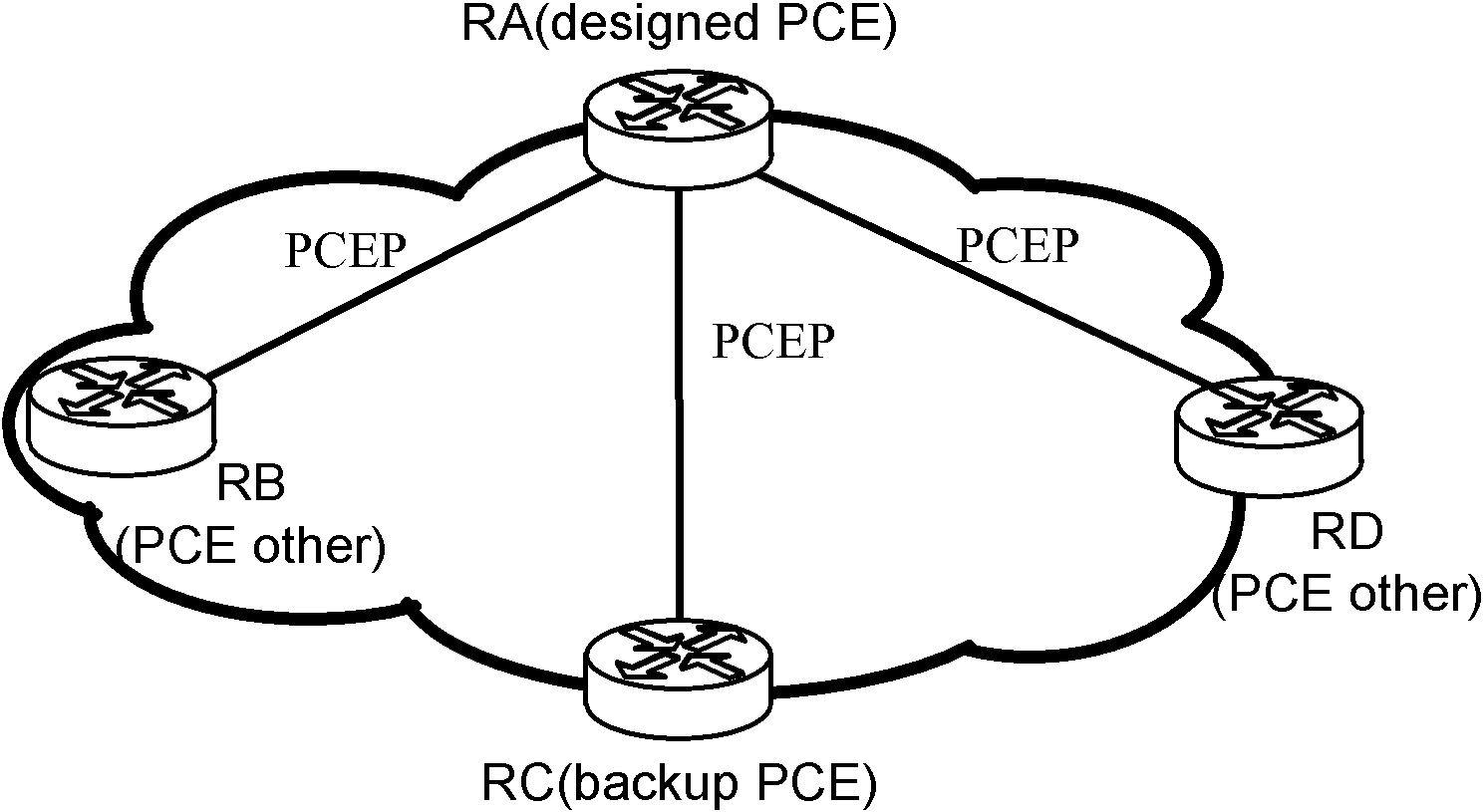
[0070] The following will further introduce the path calculation process of the above system in combination with the scene shown in the figure.

[0071] Such as figure 2 In the typical network of PCEs in the path computation domain shown in the figure, during path computation, each node device divides the PCEs in the path computation domain into the main PCE server (designed PCE) and the backup PCE server (backup PCE) according to the set selection policy. and other PCE servers (PCEother). Wherein, the set selection strategy is related to the scope and capabilities of the PCE calculation in the path calculation domain. For example, when all PCCs in the path computation domain select RA (Router A) as the primary PCE server, all path computation requests on the PCCs will be sent to RA for processing. RA synchronizes resource allocation information with other PCE servers (RB, RC and RD) through the PCEP protocol. There is no need to synchronize resource allocation information...

Embodiment 3

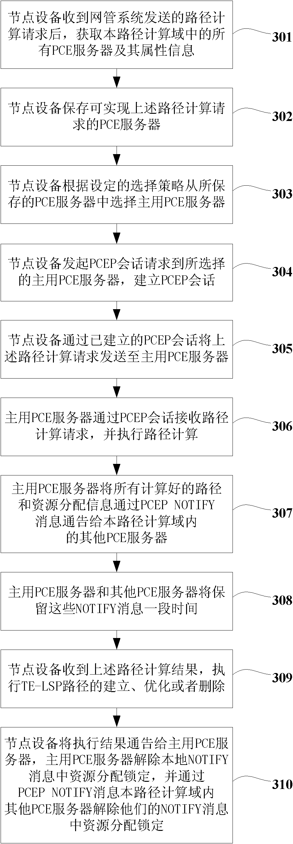
[0095] This embodiment takes Figure 5 Another typical network shown (pure optical network, two wavelengths λ1 and λ2 are configured on each TE link) illustrates the process that the node device selects the active PCE server for path calculation. For convenience, the path computation domain is configured with 4 PCE servers. The PCE server has a global TE information view, and can discover all TE link attributes and node internal attribute information in the path computation domain. The process includes the following steps:

[0096] The first step is to set up the network, configure the path protocol (OSPF-TE or ISIS-TE), configure the protocol instance, enable the protocol TE function, configure the area, configure the network segment and interface, configure the internal fiber connection, configure the transmission interface fiber connection, The network reaches a steady state.

[0097] Wherein, each first node device uses a unified selection strategy to select the active ...


PUM


Abstract

The invention relates to the field of transport network, in particular to a path calculation method, a system and node equipment. The method in the invention comprises the following steps: receiving a path calculation request by the node equipment; from a PCE ( path calculation element) server capable of performing the path calculation request in a local path calculation region, selecting a primary PCE server according to a set selection strategy; sending the path calculation request to the primary PCE server; according to the path calculation request, performing path calculation and resource distribution by the primary PCE server; and notifying path calculation and resource distribution information to other PCE servers in the path calculation region. At least one embodiment in the invention simplifies the synchronous processing flow of the integral resource distribution information of the network in the path calculation region, and improves the reliability of path calculation and resource distribution under the PCE environment.

Description

technical field [0001] The invention relates to the field of transmission networks, in particular to a path calculation method, system, and node equipment. Background technique [0002] In the transmission network, the proposal of path computing element (PCE, path compute element) and PCEP (path compute element communication protocol, PCE communication protocol) provides a feasible way for cross-domain path computing, and also provides a basis for TE LSP of different manufacturers' products. (traffic-engineering label switched path, traffic engineering label switching path) computing interconnection creates conditions. [0003] Usually, path calculation and resource allocation are two sub-problems of RWA (routing and resource assignment). After the path calculation and resource allocation are successful, the connection management submodule (CC, Connection Controller) sends a PATH message through RSVP (Resource ReServation Protocol, resource reservation protocol)-TE to estab...

Claims


Application Information

Patent Timeline
IPC IPC(8): H04L12/56H04L29/06
CPCH04L45/00
Inventor 戴文杰赵巍
Owner ZTE CORP
Why Eureka
Try Eureka