
Sintering trolley
A technology for sintering trolleys and car bodies, which is applied to furnace types, furnaces, lighting and heating equipment, etc., can solve the problems of high temperature erosion of the sintering trolley car body and wheels, and achieve the effect of strengthening the flame blocking effect of the igniter, prolonging the Service life, the effect of reducing high temperature erosion
Inactive Publication Date: 2011-03-16
徐宏亮
View PDF0 Cites 0 Cited by
- Summary
- Abstract
- Description
- Claims
- Application Information
AI Technical Summary
Problems solved by technology
[0003] The purpose of the present invention is to overcome the deficiencies of the prior art and provide a sintering trolley to solve the problem that the body and wheels of the sintering trolley are corroded by high temperature
Method used
View moreImage
Smart ImageViewing Examples

Examples
Embodiment Construction
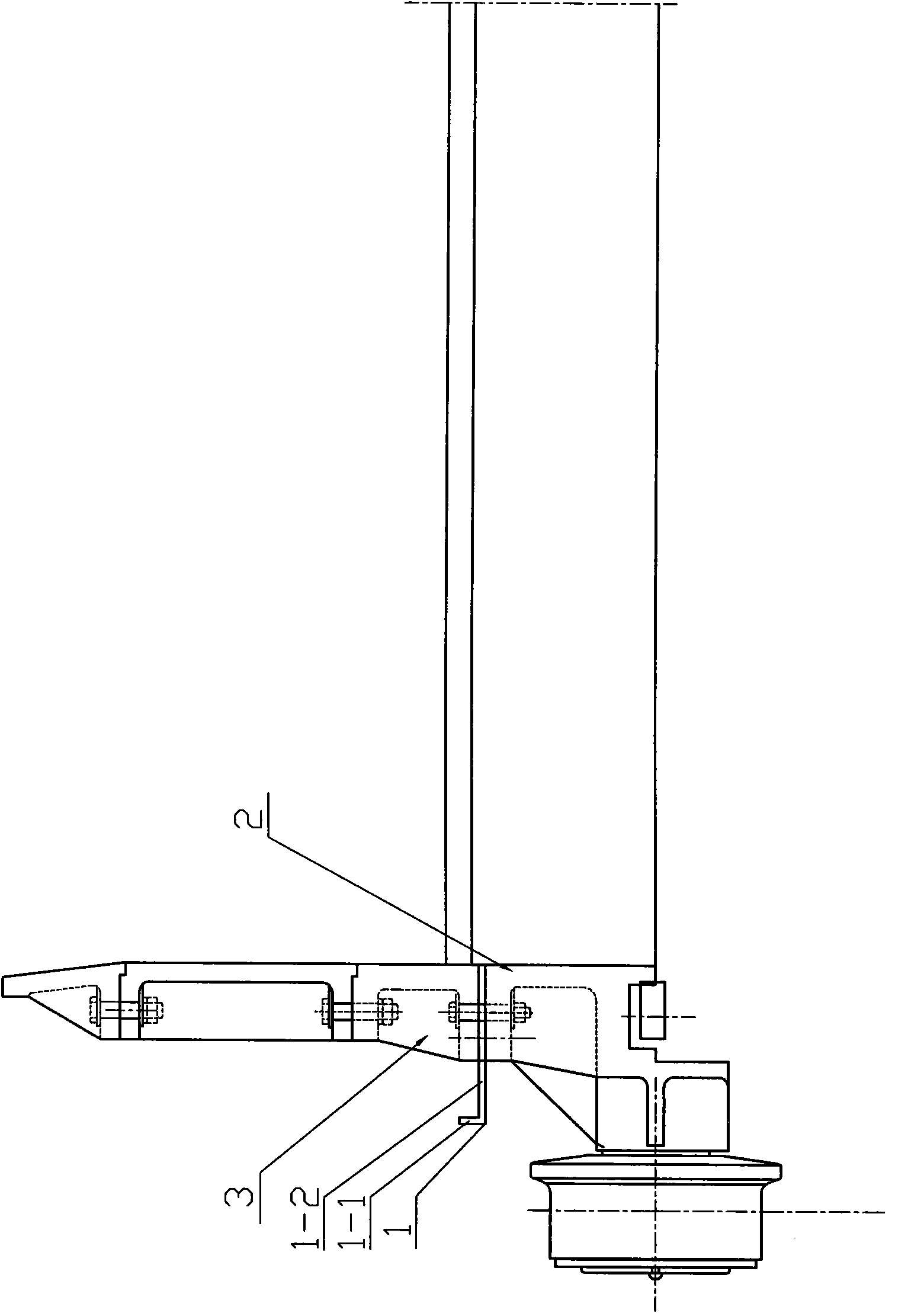
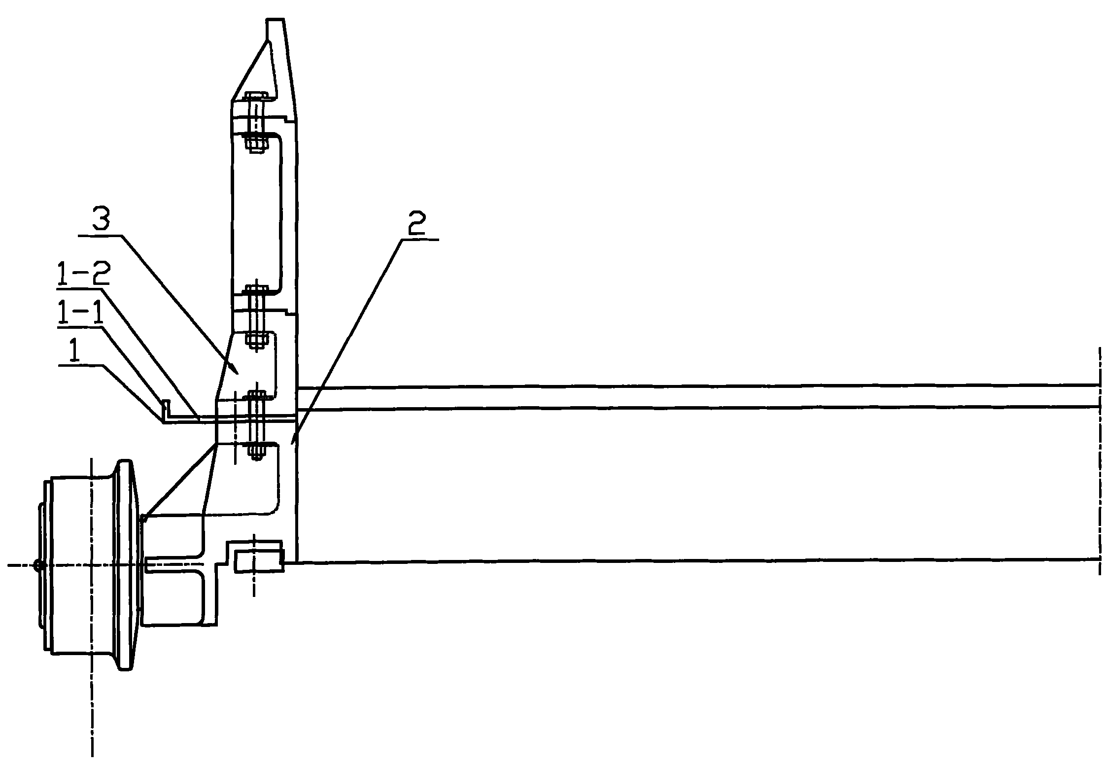
[0010] Such as figure 1 As shown, it is a sintering trolley, which includes a trolley body 2, and the upper sides of the trolley body 2 are fixedly connected with the lower fence 3 respectively, and a durable An L-shaped fire baffle 1 made of heat-resistant and corrosion-resistant materials, the L-shaped fire baffle 1 includes a longitudinal section 1-1 and a transverse section 1-2, the longitudinal section 1-1 and the transverse section 1-2 are vertically arranged, the longitudinal section 1 The lower end of -1 is fixedly connected to the outer end of the transverse section 1-2, and the inner end of the transverse section 1-2 is arranged between the trolley body 1 and the lower fence 2.
Login to View More PUM
 Abstract
The invention discloses a sintering trolley, relating to the field of technical equipment of a metallurgical machinery sintering trolley. The sintering trolley comprises a trolley body, wherein two sides above the trolley body are respectively fixedly connected with a lower breast board; an L-shaped fire damper board made of a heat-resistant anticorrosion material is arranged between the trolley body and each lower breast board respectively; and each L-shaped fire damper board comprises a longitudinal section and a transverse section, the lower end of the longitudinal section is fixedly connected with the outer end of the transverse section, and the inner end of the transverse section is arranged between the trolley body and the lower breast boards. After the fire damper boards are installed, the overflow flame of an igniter can not be directly sprayed on the trolley body and wheels, and the flanges of the fire damper boards are upward to strengthen the effect of blocking flame of the igniter, thereby reducing the high temperature corrosion to which the trolley body and the wheels are subject when the sintering trolley is in use and prolonging the service life.
Description
technical field [0001] The invention relates to the technical equipment field of metallurgical machinery sintering trolley. Background technique [0002] During the use of the sintering trolley, due to the deviation of the installation angle of the burner of the igniter, the flame is often sprayed between the trolley body and the wheel. The flame temperature is very high, which is easy to cause damage to the trolley body and wheels, shortens the service life of the trolley body and wheels, greatly increases production costs, and reduces production efficiency. Contents of the invention [0003] The object of the present invention is to overcome the deficiencies of the prior art, provide a sintering trolley, and solve the problem that the body and wheels of the sintering trolley are corroded by high temperature. The purpose of prolonging the service life of the trolley body and the wheel, improving the sintering production efficiency and reducing the production cost is real...
Claims
Login to View More Application Information
Patent Timeline
 IPC IPC(8): F27B21/08
Inventor徐宏亮
Owner徐宏亮