Magnetron sputtering device

A magnetron sputtering and sputtering technology, applied in the field of sputtering, can solve problems such as low utilization rate of target materials

Inactive Publication Date: 2011-03-30
HONG FU JIN PRECISION IND (SHENZHEN) CO LTD +1
View PDF2 Cites 14 Cited by
  • Summary
  • Abstract
  • Description
  • Claims
  • Application Information

AI Technical Summary

Problems solved by technology

When this part of the target is exhausted and needs to be replaced, there are still targets in other parts, and the utilization rate of the target is low

Method used


Image

  • Magnetron sputtering device
  • Magnetron sputtering device

Examples


Embodiment Construction

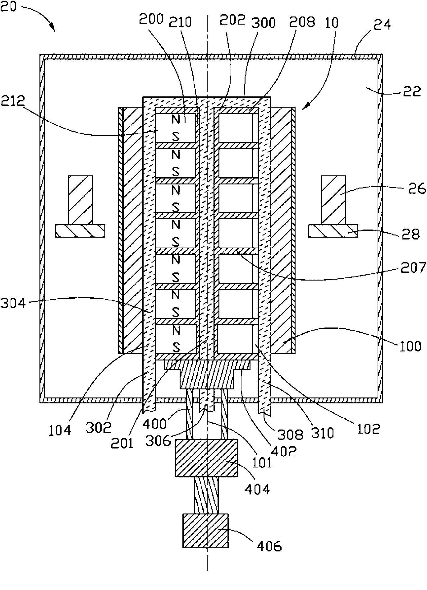
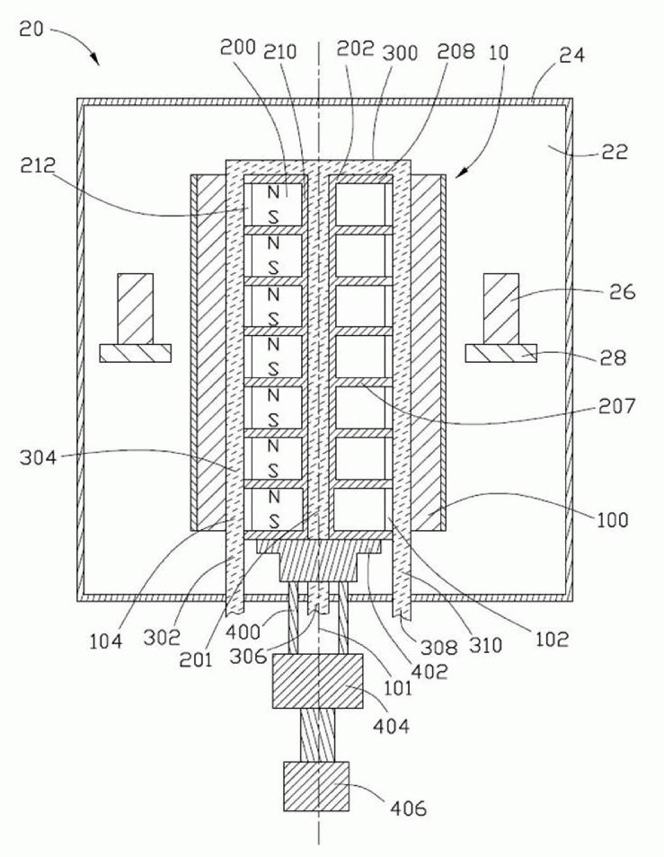
[0007] Please combine figure 1 , The magnetron sputtering device 20 of the preferred embodiment of the present invention includes a housing 24 , a target source 10 and a plurality of bases 28 . The housing 24 defines a cylindrical sputtering space 22 . The target source 10 and a plurality of seats 28 are located in the sputtering space 22 . The workpiece 26 to be sputtered can be placed on the base 28 to be sputtered in the sputtering space 22 .

[0008] The target source 10 includes a target 100 , a magnetic unit 207 , a cooling unit 300 and an actuator 400 . The target 100 is cylindrical and has a central axis 101 . The target 100 defines a cylindrical cavity 102 .

[0009] The magnetic unit 207 is disposed in the cylindrical cavity 102 defined by the target 100 along the central axis 101 . The magnetic unit 207 includes a bracket 202 and a plurality of magnetic elements 200 fixed on the bracket 202 . The bracket 202 includes a cylindrical tube 210 and a plurality of p...


PUM


Abstract

The invention provides a magnetron sputtering device, which comprises a shell for defining a sputtering space and a target source positioned in the shell. The target source comprises a cylindrical target with a central axis, a plurality of magnetic elements and an actuator. The plurality of magnetic elements are arranged in the target along the central axis. The actuator is arranged along the central axis and used for driving the plurality of magnetic elements to rotate around the central axis and move to and fro along the central axis direction. By reciprocating motion of the magnetic elements along the axial direction, the magnetic fields applied on the surface of the target become uniform. The frequency bombarded on the surface of the target becomes equal, and then the surface of the target is uniformly consumed, so the utilization rate of the target is improved.

Description

technical field [0001] The invention relates to sputtering technology, in particular to a magnetron sputtering device. Background technique [0002] A cylindrical magnetron sputtering device generally includes a cylindrical shell, a cylindrical target placed in the cylindrical shell, and a magnet group placed in the cylindrical target. The magnet group is generally composed of a plurality of independent magnets, and the magnet group forms a superimposed magnetic field. Since the plurality of magnets are independent of each other, the distribution of the superimposed magnetic field on the surface of the target is generally not uniform. During sputtering, the concentration of electrons is higher in areas with high magnetic field strength on the surface of the target, and the frequency of bombardment of this part of the target is therefore higher. After repeated use, this part of the target consumes more than other targets with low magnetic field strength. When this part of ...

Claims


Application Information

Patent Timeline
Patent Type & Authority Applications(China)
IPC IPC(8): C23C14/35
CPCH01J37/3455H01J37/3452H01J37/3405
Inventor 吴佳颖张庆州
Owner HONG FU JIN PRECISION IND (SHENZHEN) CO LTD
Why Eureka
Try Eureka