Turbine housing with wall cladding

A technology for turbine casings and baseboards, applied in mechanical equipment, engine components, machines/engines, etc., can solve the problems of unsealed joint area, uneven temperature distribution stress, uneven wall thickness of shell parts, etc. Achieving reduced temperature gradients, easy availability, and low cost

Inactive Publication Date: 2011-03-30
SIEMENS AG
View PDF4 Cites 2 Cited by
  • Summary
  • Abstract
  • Description
  • Claims
  • Application Information

AI Technical Summary

Problems solved by technology

Due to the joint flanges, the wall thickness of the housing parts is not uniform, which results in an uneven temperature distribution and thus creates stresses in the components which lead to leaks in the area of ​​the joints

Method used


Image

  • Turbine housing with wall cladding
  • Turbine housing with wall cladding
  • Turbine housing with wall cladding

Examples


Embodiment Construction

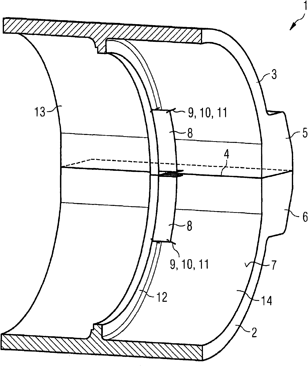
[0019] figure 1 A three-dimensional sectional view of a turbine housing according to the invention is shown. The turbine housing 1 comprises a turbine housing lower part 2 and a turbine housing upper part 3 . The two turbine housing parts 2 , 3 engage with each other in the assembled state. In this case, the joints 4 are respectively formed on the joint surfaces. In order that fluid cannot flow from the inside of the turbine housing 1 to the outside, the joint 4 must be closed as tightly as possible. For this purpose, the lower part 2 of the turbine housing and the upper part 3 of the turbine housing are firmly screwed together. For a good screwing of the two turbine housings 2 and 3 , the two turbine housing parts each have a joining flange 5 , 6 . Engagement bolt 11 (in figure 1 (not visible in ) are arranged in the joint flanges 5,6. The turbine housing 1 is sealed by screwing the two turbine housing parts 2 , 3 . On the inner side of the outer housing, webs 12 for r...


PUM


Abstract

A turbine housing (1) for a turbine is provided. The turbine housing (1) includes a wall cladding (8) on an inner wall (7) of the turbine housing. In a region of joint flanges (5, 6), the wall cladding (8) is arranged and embodied such that the wall cladding reduces convective heat transfer and thermal radiation in a region of the joint flanges (5, 6).

Description

technical field [0001] The invention relates to a turbine housing, in particular of a steam turbine, consisting of a turbine housing lower part and a turbine housing upper part, which engage one another in the assembled state and here on their joining surfaces The joints are formed in each case, each turbine housing part having a joint flange in the region of the joint, by means of which joint flanges the turbine housing parts are screwed together by means of joint screws. Background technique [0002] The outer shell of the turbine housing is generally of two-part design and comprises a lower part of the turbine housing and an upper part of the turbine housing. The two-part embodiment of the turbine housing simplifies the assembly of the rotor. The lower part of the turbine housing and the upper part of the turbine housing engage with each other via joint surfaces in the assembled state. In this case, the lower part of the turbine housing and the upper part of the turbine...

Claims


Application Information

Patent Timeline
Patent Type & Authority Applications(China)
IPC IPC(8): F01D25/26
CPCF01D25/145
Inventor K·洛赫纳M·施特劳赫
Owner SIEMENS AG
Why Eureka
Try Eureka