Backlight module

A backlight module and backplane technology, which is applied in the direction of electric light source, light source fixing, and damage prevention measures for lighting devices, etc., can solve the problems of reducing the optical performance of the backlight module, prone to scratches, limited effect, etc., and achieve the goal of improving the optical performance Effect

Active Publication Date: 2011-03-30
AU OPTRONICS CORP
View PDF3 Cites 5 Cited by
  • Summary
  • Abstract
  • Description
  • Claims
  • Application Information

AI Technical Summary

Problems solved by technology

[0003] However, these optical films are prone to scratches when the backlight module or liquid crystal display is subjected to vibration tests. Therefore, the existing methods to avoid scratches on the optical films are mostly to place the optical films above the light guide plate in a hanging manner. to reduce optical diaphragm movement, however this has limited effect
There is also a liquid crystal display module that uses light-emitting diodes as light sources and has thinner features. The optical film and the light guide plate (or between the optical films) are closer, which is more likely to cause scratches
[0004] In addition, if the optical film is completely fixed, such as by adhesive fixation or restricted by structure, it is easy to cause wave-like problems on the optical film due to uneven force, which further reduces the optical performance of the backlight module.

Method used


Image

  • Backlight module
  • Backlight module
  • Backlight module

Examples


Embodiment Construction

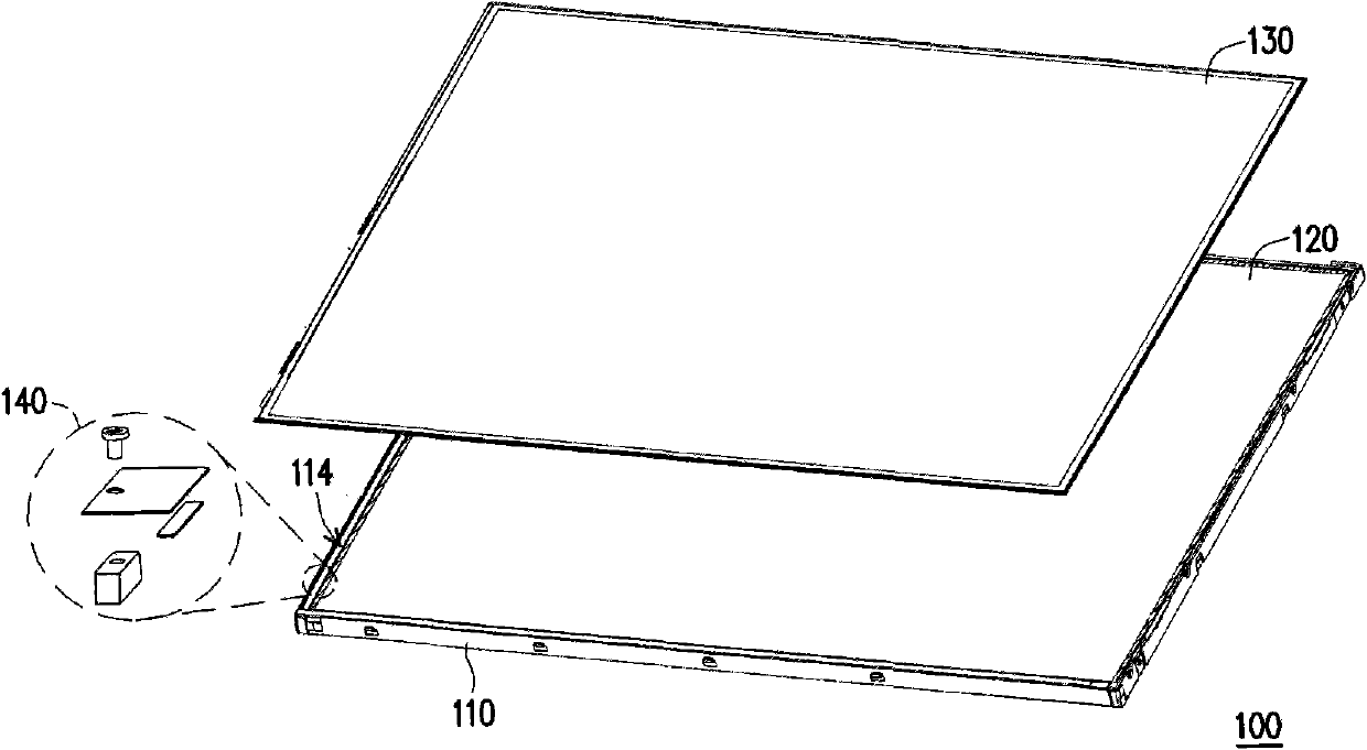
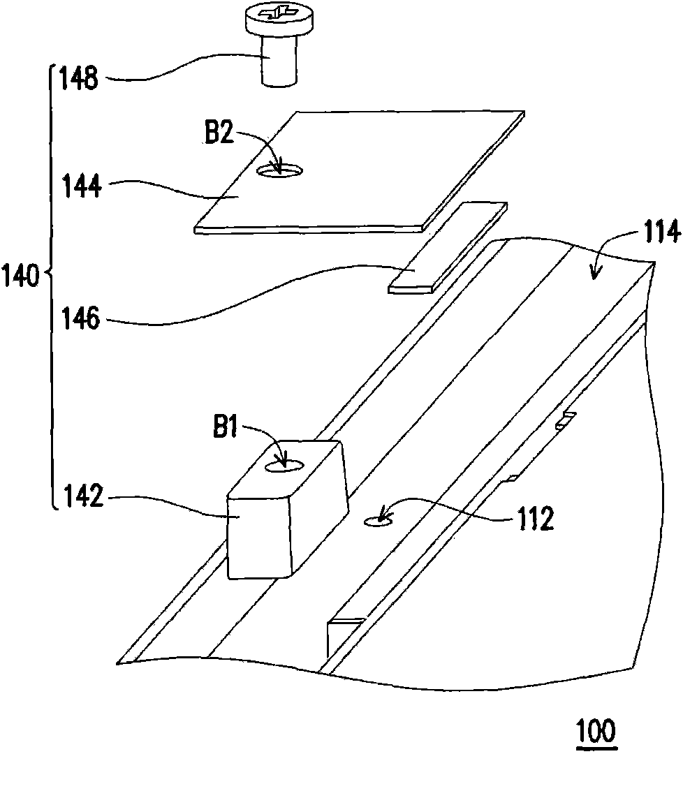
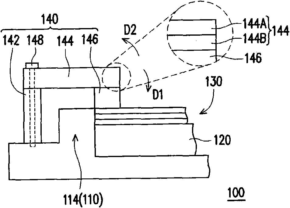
[0057] Figure 1A It is an exploded view of a backlight module according to an embodiment of the present invention. Figure 1B yes Figure 1A A partial enlargement of the . Figure 1C yes Figure 1B The cross-sectional view of the assembled backlight module, in which some components are asymmetrically enlarged to clearly identify the relevant components. Please also refer to Figure 1A to Figure 1C , in this embodiment, the backlight module 100 includes a backplane 110 , a light guide plate 120 , a plurality of optical films 130 and a clamping device 140 . The light guide plate 120 is disposed in the area surrounded by the edge structure 114 of the backplane 110, and the backplane 110 can be made of metal or plastic. The optical film 130 is disposed on the light guide plate 120 . The clamping device 140 includes a support piece 142 , a clamping piece 144 and a buffer piece 146 . The supporting member 142 protrudes from the backplane 110 and may be a metal bump or a plasti...


PUM

PropertyMeasurementUnit
Young's modulusaaaaaaaaaa
Thicknessaaaaaaaaaa

Abstract

The invention discloses a backlight module which comprises a back plate, a light guide plate, a plurality of optical diaphragms and a clamping device, wherein the light guide plate is arranged in a region surrounded by the edge structures of the back plate; the optical diaphragms are arranged on the light guide plate; the clamping device comprises a supporting part, a clamping piece and a buffer part; the supporting part is bulged out of the back plate; the clamping piece is arranged on the supporting part and extends from the back plate toward the optical diaphragms; and the buffer part is arranged between the clamping piece and the optical diaphragms.

Description

technical field [0001] The present invention relates to a clamping device, and in particular to a clamping device arranged on a backlight module. Background technique [0002] In liquid crystal displays, cold cathode fluorescent tubes (Cold Cathode Fluorescent Tube, CCFT) or light emitting diodes (Light Emitting Diode, LED) are generally used as light sources, and then the light emitted by the light sources is guided to the display screen through the light guide plate. In order to prevent the uneven brightness of the liquid crystal display, it is necessary to use an optical film to make the brightness of the entire screen uniform, and to maintain the brightness of the entire screen without compromising the brightness of the light source. In the current backlight module, optical films such as diffusers are mainly used to achieve uniformity and concentration of light. [0003] However, these optical films are prone to scratches when the backlight module or liquid crystal disp...

Claims


Application Information

Patent Timeline
IPC IPC(8): F21S8/00F21V15/04F21V17/10
Inventor 许敦皓沈昌和李国志
Owner AU OPTRONICS CORP
Why Eureka
Try Eureka