Secondary encapsulated waterproof process and structure of liquid crystal display (LCD) face frame

A waterproof structure and secondary packaging technology, which is applied in optics, instruments, nonlinear optics, etc., can solve the problems of labor-consuming and time-consuming installation of operators, increased production costs, high cost of large touch screens, etc., and achieve a good waterproof effect Effect

Inactive Publication Date: 2011-03-30
TOUCH VIDEO MONITOR CORP
View PDF4 Cites 4 Cited by
  • Summary
  • Abstract
  • Description
  • Claims
  • Application Information

AI Technical Summary

Problems solved by technology

At present, the structure of the touch screen produced by large touch screen manufacturers is to paste FOAM TAPE (foam bead) such as figure 1 As shown, the touch screen A1 is set in the outer frame B1, and the outer frame is provided with an annular groove along the periphery of the touch screen. The FOAM TAPE C1 is pasted in the annular groove and the touch screen is close. It is dustproof but not waterproof, and it is time-consuming to paste FOAM TAPE; there is also a touch screen structure such as WIPER BLADE (wiper strip) figure 2 As shown, the structure of the outer frame B2 is similar to the previous one. The outer frame is provided with an annular groove along the periphery of the touch screen. The WIPER BLADE C2 is inserted into the annular groove and is close to the touch screen A2. Since the WIPER BLADE is The hard material has a certain waterproof and dustproof effect, but it requires labor-intensive and time-consuming installation by the operator during production, and it is easy to damage the touch screen due to the poor cooperation between the WIPER BLADE and the touch screen due to human reasons. The cost of the screen is high, once damaged it will increase the production cost

Method used


Image

  • Secondary encapsulated waterproof process and structure of liquid crystal display (LCD) face frame
  • Secondary encapsulated waterproof process and structure of liquid crystal display (LCD) face frame
  • Secondary encapsulated waterproof process and structure of liquid crystal display (LCD) face frame

Examples


Embodiment

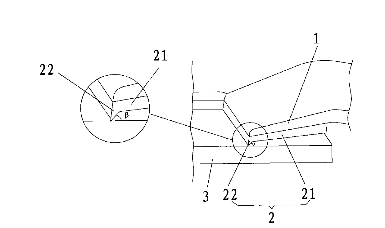
[0025] Example: see Figure 3 to Figure 7 , a secondary glue-coated waterproof structure for an LCD surface frame, comprising a plastic shell surface frame 1 and a waterproof plastic inner frame 2 integrated with it by injection molding, and the waterproof plastic inner frame 2 is distributed along the annular inner edge of the plastic shell surface frame 1 and combined as a whole , and the waterproof plastic inner frame extends toward the touch screen 3 in the LCD frame and touches against the surface of the touch screen to form a waterproof structure.

[0026] see image 3 , the waterproof plastic inner frame 2 is composed of a plastic main body 21 and a composite plastic waterproof end 22. The plastic waterproof end 22 is a sharp corner formed by the extension of the plastic main body 21 to the touch screen, and the contact angle β with the touch screen is Between 50±10°, the thickness of the plastic body of the waterproof plastic inner frame is 1.5±0.2mm.

[0027] see ...


PUM

PropertyMeasurementUnit
thicknessaaaaaaaaaa
hardnessaaaaaaaaaa

Abstract

The invention discloses a secondary encapsulated waterproof process and structure of a liquid crystal display (LCD) face frame. The structure comprises a plastic casing face frame and a waterproof plastic inner frame integrated with the plastic casing face frame by injection molding, wherein the waterproof plastic inner frame is distributed and combined along the annular inner edge of the plastic casing face frame, and the waterproof plastic inner frame extends to a touch control screen in the LCD face frame and is in contact with the surface of the touch control screen to form a waterproof structure. In the waterproof LCD manufacturing process, a first mold is firstly used for forming the plastic casing face frame by injection molding, and then, another mold is used for forming the waterproof plastic inner frame on the plastic casing face frame by injection molding and enabling the waterproof plastic inner frame to be matched with a positioning column on the plastic casing face frame, so that the face frame and the touch control screen form the waterproof structure. The plastic casing of the machine of the invention is formed by secondary molding, and waterproof plastics are directly injected inside the casing by injection molding, thereby achieving the waterproof effect when the water is poured on the screen imprudently. In the invention, after a finished product is assembled, the touch control can not be influenced.

Description

technical field [0001] The invention discloses a secondary glue-encapsulating waterproof process and structure of an LCD surface frame, which belongs to the technical field of electronic and electrical display manufacturing according to the International Patent Classification (IPC), and especially relates to large electronic appliances such as displays, LCD / LED TVs or touch monitors. Display device screen waterproof structure. Background technique [0002] The touch screens of large electronic and electrical display devices generally do not have a waterproof design, and the structure is that the touch screen is directly installed in the surrounding frame. At present, the structure of the touch screen produced by large touch screen manufacturers is to paste FOAM TAPE (foam bead) such as figure 1 As shown, the touch screen A1 is set in the outer frame B1, and the outer frame is provided with an annular groove along the periphery of the touch screen. The FOAM TAPE C1 is pasted...

Claims


Application Information

Patent Timeline
Patent Type & Authority Applications(China)
IPC IPC(8): G02F1/13H05K5/06
Inventor 范仁鹏陈治军
Owner TOUCH VIDEO MONITOR CORP
Why Eureka
Try Eureka