Part feeder for chip mounting device

A chip mounting and feeder technology, applied in the direction of electrical components, electrical components, etc., to achieve the effect of preventing wrong mounting, and quick and easy mounting operations

Inactive Publication Date: 2011-03-30
JUKI CORP
View PDF4 Cites 4 Cited by
  • Summary
  • Abstract
  • Description
  • Claims
  • Application Information

AI Technical Summary

Problems solved by technology

[0004] Here, in the conventional electric parts feeder of this kind, since the power is supplied from the mounted mounting device, it is not possible to display the parts feeder in the state where the parts feeder is detached from the mounting device. independent action including the display of the

Method used


Image

  • Part feeder for chip mounting device
  • Part feeder for chip mounting device
  • Part feeder for chip mounting device

Examples


Embodiment Construction

[0021] Hereinafter, one embodiment of the present invention will be described with appropriate reference to the drawings.

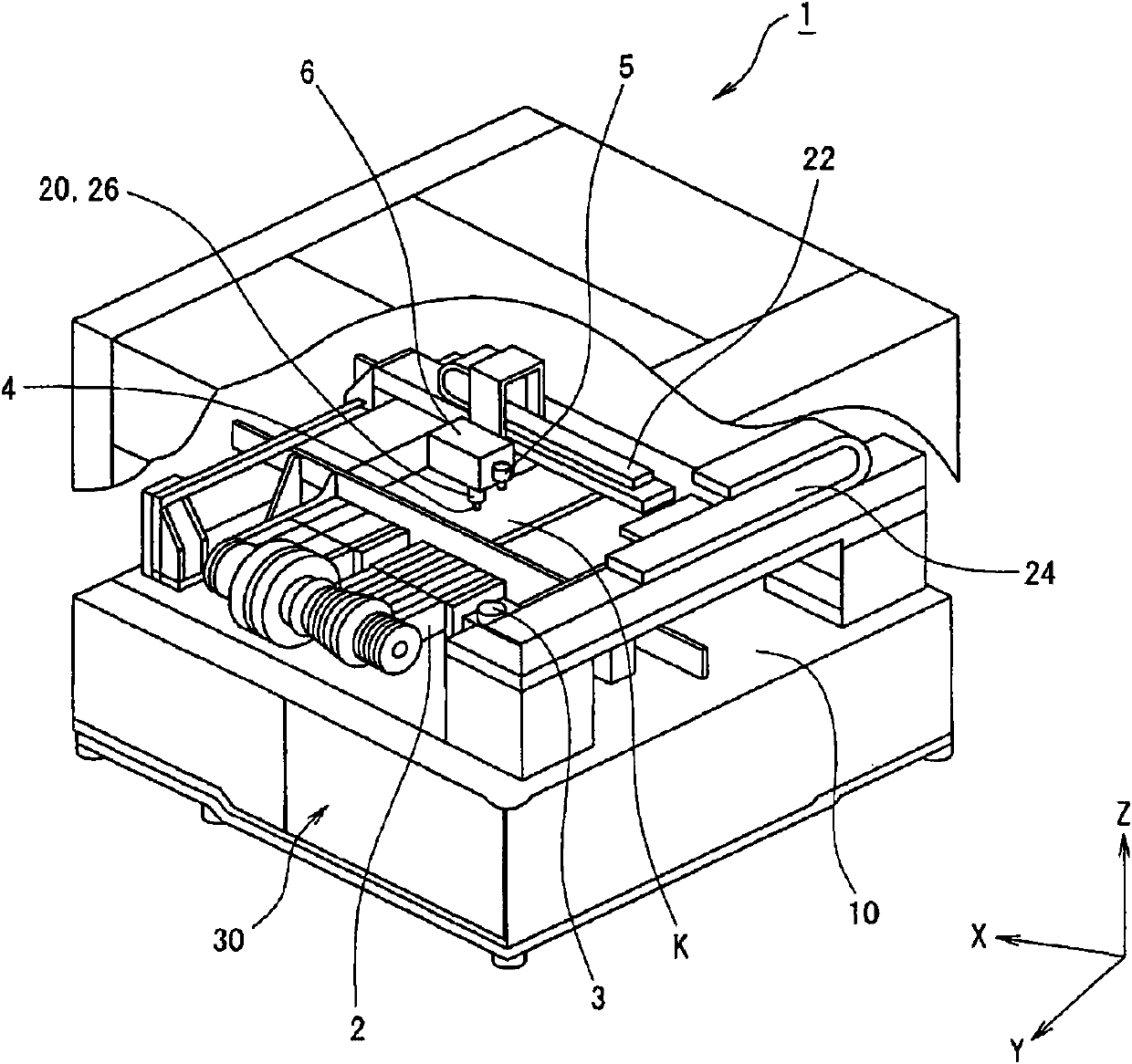
[0022] Such as figure 1 As shown, the chip mounting apparatus 1 is provided with a component feeder 2 and a component recognition camera 3 as a plurality (for example, 60) of electric component supply devices for supplying electronic components (not shown) on the lower side of the figure. In addition, a substrate transfer device 10 for carrying in and carrying out the substrate K extends in the left-right direction at a substantially central portion in the drawing, and the substrate K is placed on the substrate transfer device 10 . In addition, the component mounting head 6 is disposed above the substrate transfer device 10 . The component mounting head 6 is provided with a suction nozzle 4 for suctioning mounted electronic components, and a substrate recognition camera 5 capable of photographing substrate marks and electronic components on the substrate...


PUM


Abstract

The present invention provides a part feeder, capable of preventing error installation in mounting of the part feeder to a mounting device, and easily and rapidly mounting. The part feeder has a display part (58), a control part (54) and a power supply part (56). When an external power supply of a chip mounting device is switched off, the control part (54) displays a mounting position of the part feeder in a display part (58) according to mounting position information of the part feeder obtained from the chip mounting device in advance.

Description

technical field [0001] The present invention relates to an electric component supply device (hereinafter referred to as "component feeder") that supplies mounted components to an electronic component mounting device (hereinafter referred to as "chip mounting device") that mounts electronic components on a substrate. Specifically, it relates to a component feeder capable of performing mounting work more easily and quickly when the component feeder is mounted on such a chip mounting apparatus. Background technique [0002] In such a chip mounting apparatus, a component mounting head having suction nozzles is provided, and a plurality of component feeders for supplying mounted components are mounted. In addition, with respect to the substrate positioned at a predetermined position of the chip mounting device, the component mounting head absorbs electronic components from each component feeder with suction nozzles, and repeats mounting and suction of electronic components to pre...

Claims


Application Information

Patent Timeline
Patent Type & Authority Applications(China)
IPC IPC(8): H05K13/02H05K13/04
Inventor 平泉秀显
Owner JUKI CORP
Why Eureka
Try Eureka