Split adjustable knee joint fixer

An adjustable knee joint technology, used in stereotaxic surgical instruments, medical science, surgery, etc., can solve problems affecting surgical operations, patient limb instability, waste of manpower, etc., to improve surgical efficiency, eliminate limb instability, The effect of saving manpower

Inactive Publication Date: 2011-04-06
谷文光
View PDF4 Cites 2 Cited by
  • Summary
  • Abstract
  • Description
  • Claims
  • Application Information

AI Technical Summary

Problems solved by technology

[0003] The present invention solves the problem of manually fixing the patient’s knee joint at a specific angle during knee joint surgery, which wastes manpower, and the patient’s knee joint fixation angle changes due to physical decline, and the patient’s limbs are unstable and move, which affects the surgical operation. Propose a Split Type Adjustable Knee Joint Fixator

Method used


Image

  • Split adjustable knee joint fixer
  • Split adjustable knee joint fixer
  • Split adjustable knee joint fixer

Examples


specific Embodiment approach 1

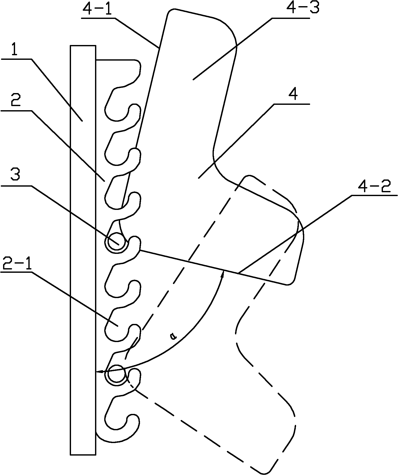
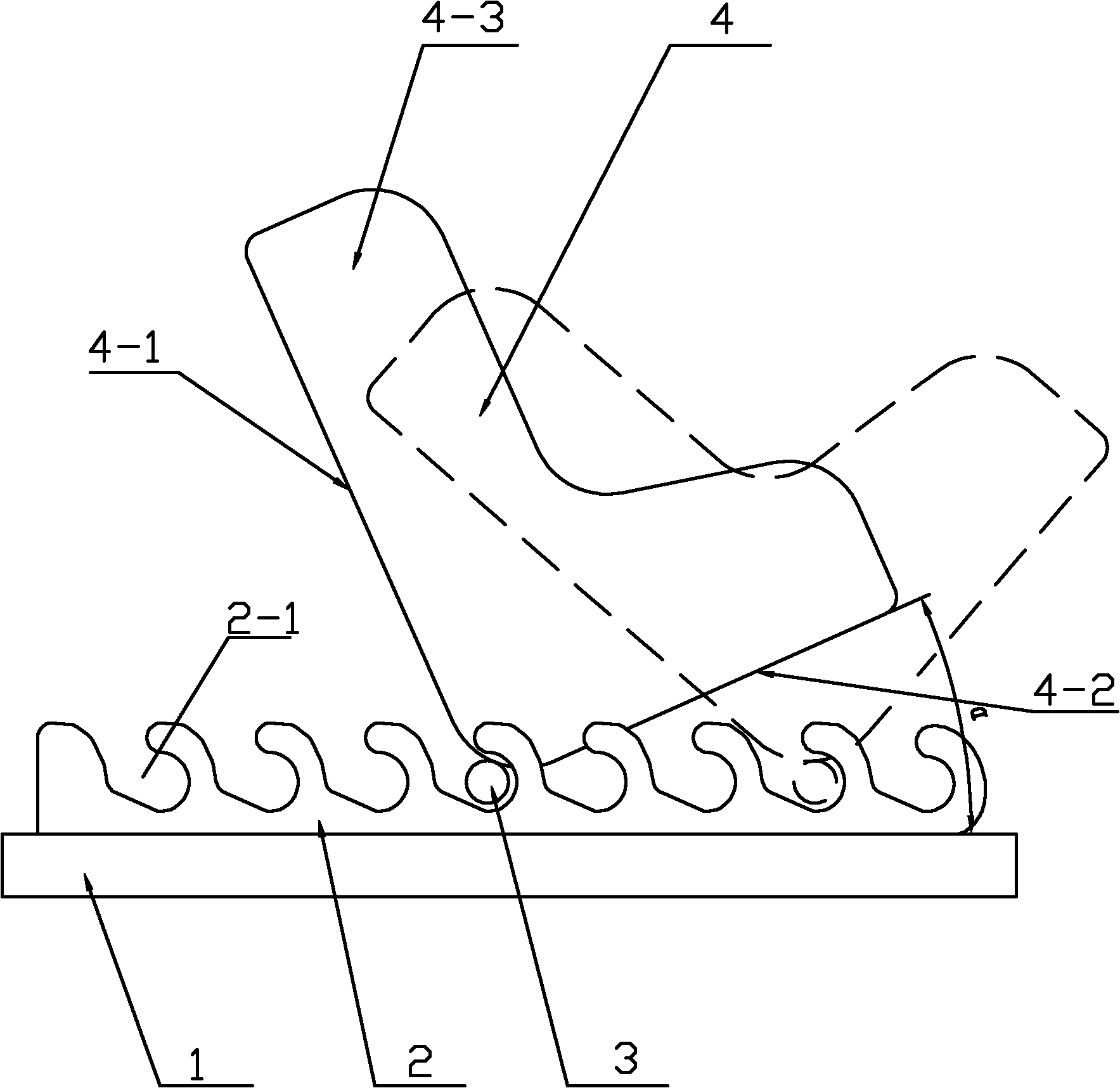
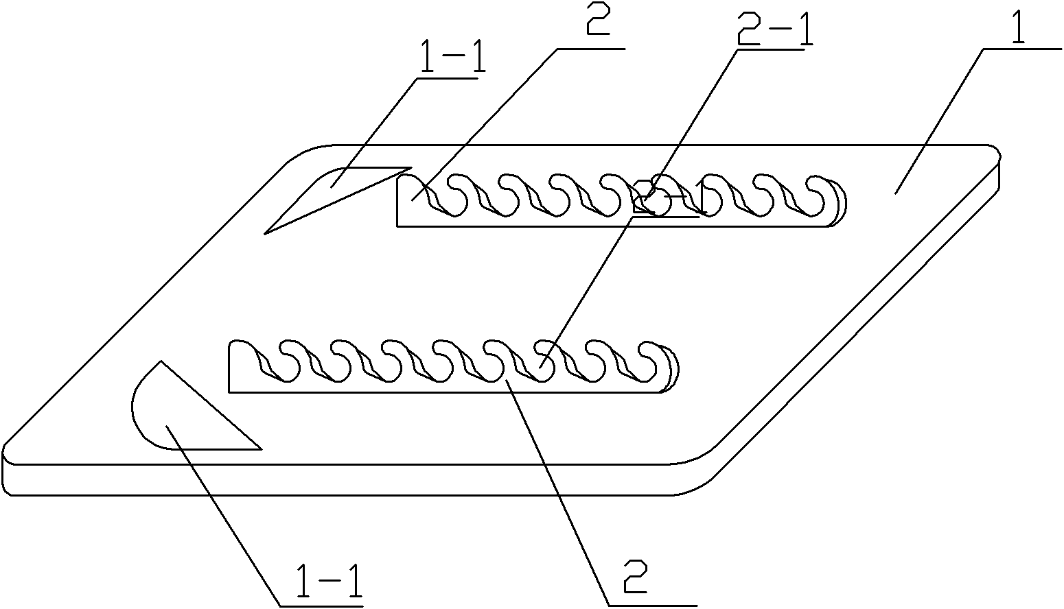
[0007] Specific implementation mode one: as Figure 1-5 As shown, a split-type adjustable knee fixator described in this embodiment includes a base plate 1, two positioning bars 2, an adjustment shaft 3 and a fixing shoe 4, and each positioning bar 2 is provided with several card slots 2- 1. The shape of each positioning bar 2 is jagged, and the back end faces of the two positioning bars 2 are arranged side by side and parallel on the upper end face of the bottom plate 1 and fixedly connected with the upper end face of the bottom plate 1. The adjustment shaft 3 and the heel of the fixed shoe 4 The fixed shoe 4 is located between the two positioning bars 2, and the two ends of the adjustment shaft 3 are respectively clamped in the corresponding slots 2-1 on a positioning bar 2. This embodiment ensures that during the knee joint operation, when the posture of the patient's thigh remains unchanged, by changing the adjustment shaft 3, that is, the adjustment shaft 3 is in the slot...

specific Embodiment approach 2

[0008] Specific implementation mode two: as Figure 1-5 As shown, the fixed boot 4 of a split-type adjustable knee joint fixer described in this embodiment includes a curved vertical plate 4-1, a sole support plate 4-2 and two L-shaped side plates 4-3, two L-shaped side plates 4-3 The side plates 4-3 are vertically arranged side by side on the upper surface of the sole support plate 4-2, and the lower ends of the two L-shaped side plates 4-3 are fixedly connected to the front edge and the rear end edge of the sole support plate 4-2 respectively. , the lower end of the curved surface vertical plate 4-1 is affixed to the side edge of the sole support plate 4-2, and the two side edges of the curved surface vertical plate 4-1 are respectively connected to the side ends of the two L-shaped side plates 4-3 The edges are fixed, and the curved surface contour of the curved surface vertical plate 4-1 is consistent with the outer contour of the calf of the human body. This embodiment e...

specific Embodiment approach 3

[0009] Specific implementation mode three: as Figure 1-5 As shown, two semicircular through holes 1-1 are opened at one end of the bottom plate 1 of the one-piece adjustable knee joint fixer described in this embodiment. This embodiment guarantees the operation process of the knee joint. The base plate 1 can be fixed on the operating table with a surgical towel or gauze to ensure that the patient’s limbs remain stable during the operation, the fixed angle of the patient’s knee joint remains unchanged, and the base plate 1 will not be affected by the patient The leg slides freely due to the strength it implements, which in turn affects the operation. Other components and connections are the same as those in the first embodiment.


PUM


Abstract

The invention relates to a knee joint fixer, in particular to a split adjustable knee joint fixer, aiming at solving the problems that the labor force is wasted by manually fixing a knee joint of a patient at the specific angle in the knee joint operation, and the operation is influenced because the fixed angle of the knee joint of the patient changes and the limb body of the patient is instable due to the physical draining. The knee joint fixer comprises a base plate, two positioning strips, an adjusting shaft and a fixing boot, wherein each positioning strip is provided with a plurality of clamping grooves and is serrated in the appearance; the end faces on the backs of two positioning strips are arranged on the upper end face of the base plate in parallel and are fixedly connected with the upper end face of the base plate; the adjusting shaft is fixedly connected with the heel part of the fixed boot which is positioned between the two positioning strips; and two ends of the adjusting shaft are respectively clamped in a corresponding clamping groove on one positioning strip. The invention is used for fixing the knee joint and ankles of the patient in the knee joint operation.

Description

technical field [0001] The invention relates to a knee joint fixer, in particular to a split-type adjustable knee joint fixer. Background technique [0002] In knee joint surgery, it is necessary to fix the knee joint at a specific angle to facilitate the operation. At present, in knee joint surgery, the doctor's assistant mainly fixes the patient's knee joint at a specific angle. During the operation, the doctor's assistant Always maintain the same posture to ensure that the patient’s knee joint and limbs remain stable. Due to maintaining the same posture for a long time, the physical strength of the doctor’s assistant will decrease, which will lead to changes in the fixed angle of the patient’s knee joint, and the patient’s limbs will be unstable and move, which will affect the operation. operation, and even cause medical malpractice. Contents of the invention [0003] The present invention solves the problem of manually fixing the patient’s knee joint at a specific ang...

Claims


Application Information

Patent Timeline
Patent Type & Authority Applications(China)
IPC IPC(8): A61B19/00A61B17/56A61B90/10
Inventor 谷文光刘慧
Owner 谷文光
Why Eureka
Try Eureka