Cylindrical transverse flux linear motor of zigzag ring winding structure

A technology of toroidal winding and transverse magnetic flux, applied in electrical components, electromechanical devices, electric components, etc., can solve the problem of long magnetic path of the mutual inductance effect magnetic field, and achieve the effect of simple structure, improved efficiency and reduced eddy current loss.

Active Publication Date: 2011-04-06
HARBIN INST OF TECH
View PDF0 Cites 7 Cited by
  • Summary
  • Abstract
  • Description
  • Claims
  • Application Information

AI Technical Summary

Problems solved by technology

[0003] In order to solve the defects of the mutual inductance effect between the phase windings and the long magnetic path of the magnetic field generated by each phase winding in the existing transverse flux linear motor, the present invention designs a cylindrical transverse flux with a meandering ring winding structure. Linear Motor

Method used


Image

  • Cylindrical transverse flux linear motor of zigzag ring winding structure
  • Cylindrical transverse flux linear motor of zigzag ring winding structure
  • Cylindrical transverse flux linear motor of zigzag ring winding structure

Examples


specific Embodiment approach 1

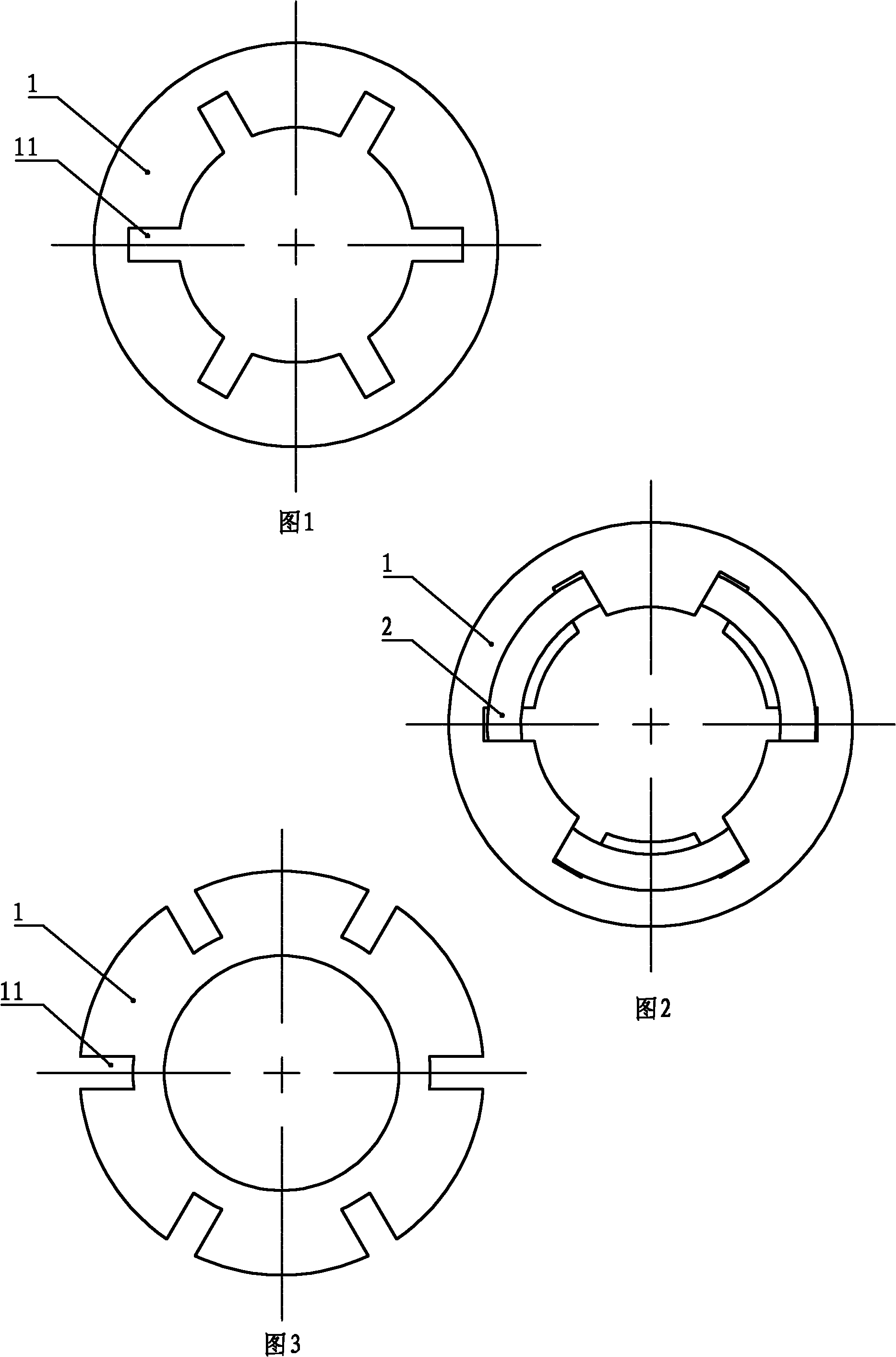
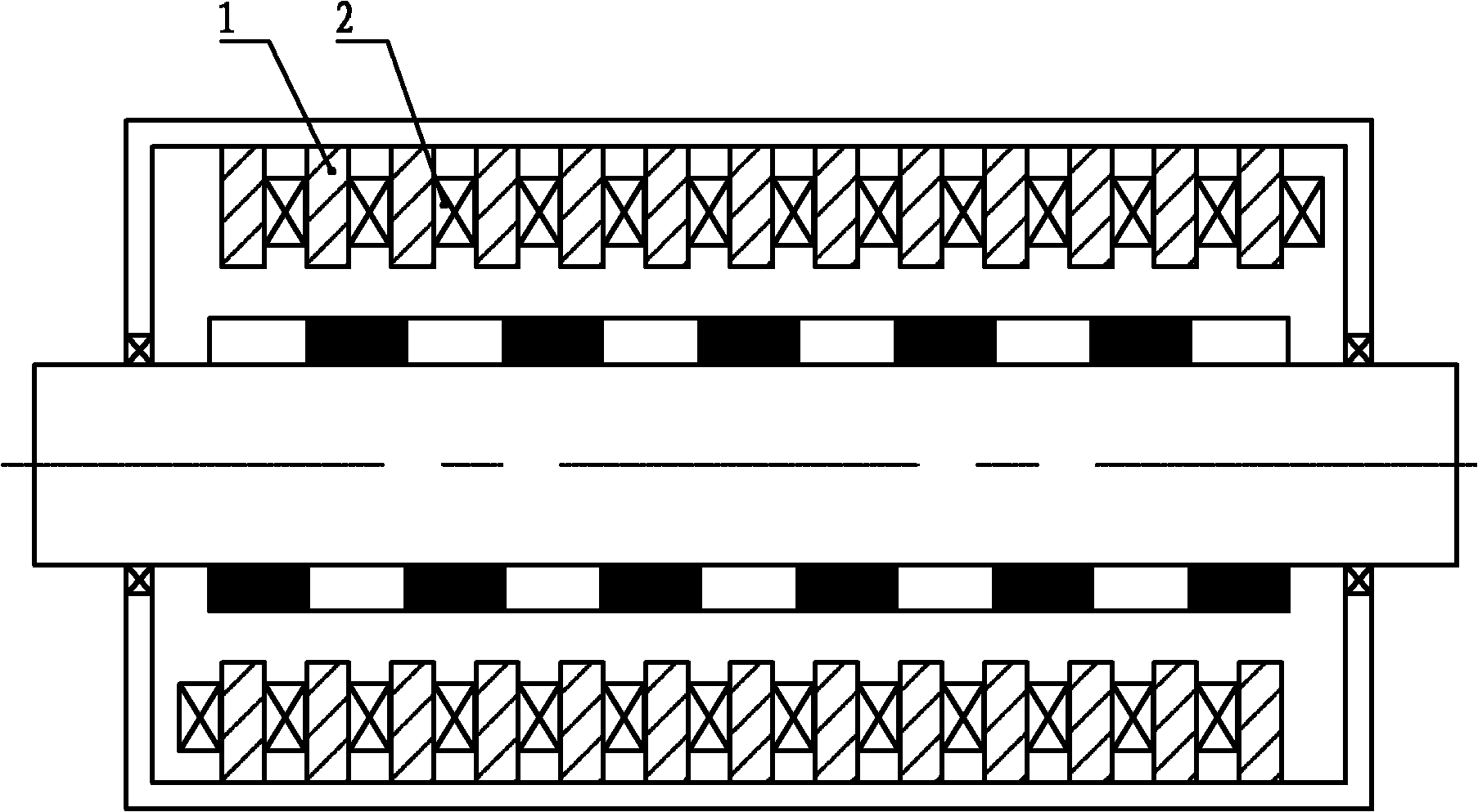
[0008] Specific implementation mode one: see figure 1 . The cylindrical transverse magnetic flux linear motor with meandering ring winding structure in this embodiment is composed of a primary, a secondary and an air gap. The primary includes a plurality of annular core units 1 and windings. The windings are composed of a plurality of coils 2. Its characteristics That is, there are 2n grooves 11 arranged in the radial direction on the air gap side of the annular core unit 1, where n is a positive integer, and the 2n grooves 11 are evenly distributed along the circumferential direction, and a plurality of annular iron cores The units 1 are evenly arranged inside the cylindrical casing along the axial direction, and there is a gap between every two adjacent annular core units 1 to form a slot for embedding coils. Each annular core unit 1 A coil 2 is wound on it, and the coil 2 is evenly divided into 2n effective segments 21 along the circumference, and between each two adjacen...

specific Embodiment approach 2

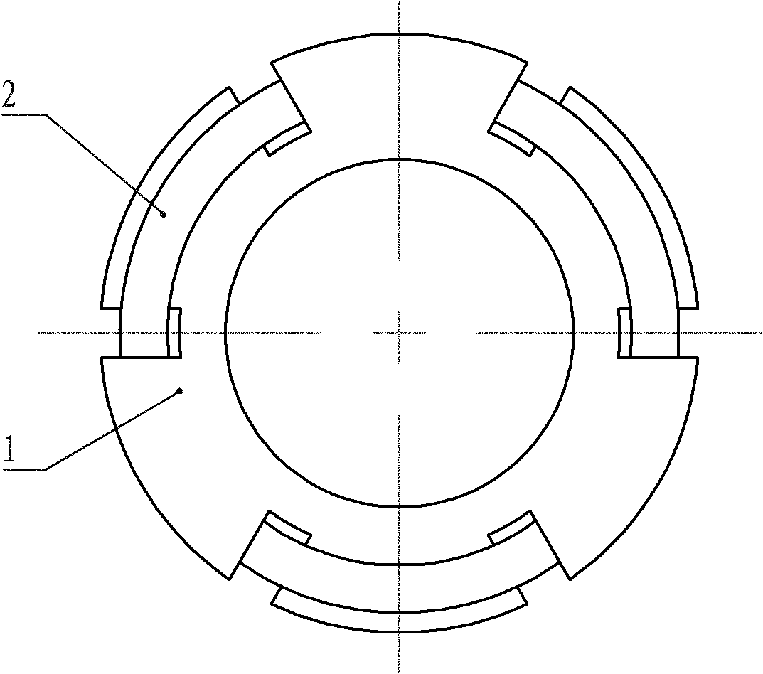
[0013] Embodiment 2: The main difference between this embodiment and the cylindrical transverse flux linear motor with meandering ring winding structure described in Embodiment 1 is that the stator core in the primary is cylindrical, and the multiple coils in the primary are 2 Evenly distributed along the circumferential direction and fixed on the air gap side of the stator core, the structure of the coil 2 is the same as that described in Embodiment 1. The specific structure of the linear motor described in this embodiment is: it consists of a primary, a secondary and an air gap , the primary includes an iron core and a winding, the winding is composed of a plurality of coils 2, and the plurality of coils 2 are evenly distributed in the axial direction and fixed on the inner surface of the cylindrical iron core, characterized in that the iron core is cylindrical , each annular meander coil 2 is composed of 2n effective segments 21 and 2n slot-spanning segments 22, wherein the ...

specific Embodiment approach 3

[0018]Specific embodiment three: this embodiment is a further definition of the secondary in the linear motor described in specific embodiment one or two, the secondary includes a permanent magnet array, and the specific structure of the permanent magnet array is: the permanent magnet The array is a cylindrical array structure composed of a plurality of tile-shaped permanent magnets 31. There are 2n tile-shaped permanent magnets 31 on each circumference, and each tile-shaped permanent magnet 31 is radially magnetized, and each tile The magnetization direction of the tile-shaped permanent magnet 31 and its axially adjacent and circumferentially adjacent tile-shaped permanent magnets 31 are all different.

[0019] When n=3, the expanded view of the permanent magnet array described in this embodiment can be found in Figure 10 As shown, the number of rows of the permanent magnet array along the axial direction can be determined according to actual needs, Figure 10 Shown is the ...


PUM


Abstract

The invention discloses the cylindrical transverse flux linear motor of a zigzag ring winding structure, relating to the motor technology. The motor of the invention can be use for solving the defects of the mutual-inductance effect existing among windings of the traditional similar motor and the long magnetic field circuit caused by the windings. The air gap side of each annular iron core unit is radially provided with 2n-numbered grooves evenly distributed in the circumferential direction, a trough for embedding a coil is formed between every two axially adjacent annular iron core units, the coil wound around each annular iron core unit is evenly divided into 2n-numbered effective sections in the circumferential direction, a trough-crossing section is formed between every two adjacent effective sections, each trough-crossing section is embedded in one groove of the iron core, and two adjacent effective sections are respectively positioned at both sides of the annular iron core unit. The invention provides another motor which is not provided with the iron core unit, and is used for directly fixing a zigzag coil onto the side wall of the cylindrical iron core close to the secondary side. The motor of the invention can be used as both a motor and a generator, thereby having wide application prospects.

Description

technical field [0001] The invention relates to motor technology, in particular to a cylindrical permanent magnet linear synchronous motor. Background technique [0002] The structure of the existing longitudinal flux cylindrical permanent magnet linear synchronous motor is as follows: Figure 18 shown. When the armature core is made of silicon steel sheets, since the direction of the laminations is axial, the direction of the armature magnetic field generated by the permanent magnet and the winding is partly in the same direction as the laminations, forming a large eddy current in the core, resulting in a larger Large eddy current loss, and the iron core lamination process is complicated, and the processing cost is high; if a solid iron core is used, although the process is simple and the cost is low, the iron core will generate greater eddy current loss, which greatly reduces the efficiency of the motor. At the same time, due to the existence of magnetic coupling between ...

Claims


Application Information

Patent Timeline
IPC IPC(8): H02K41/03
Inventor 寇宝泉张鲁白相林
Owner HARBIN INST OF TECH
Why Eureka
Try Eureka