
Inductive power supply device, inductive power supply system and control method of inductive power supply system

A power supply device and power supply system technology, applied in the direction of circuit devices, electromagnetic wave systems, electrical components, etc., can solve the problems of power waste and insufficient power supply of inductive power supply devices, and achieve the effect of saving human operations

Active Publication Date: 2011-04-13
TSANN KUEN ZHANGZHOU ENTERPRISE CO LTD
View PDF0 Cites 9 Cited by
  • Summary
  • Abstract
  • Description
  • Claims
  • Application Information

AI Technical Summary

Problems solved by technology

However, in order to enable an inductive power supply device with an electric power specification to safely supply power to different inductive electrical devices, the user must manually identify the applicable inductive electrical device for use.
Once the user is negligent, the power consumption of the inductive electrical device is greater than the power supply of the inductive power supply device, and there will be insufficient power supply; on the contrary, it will cause the problem of waste of electric energy of the inductive power supply device

Method used


Image

  • Inductive power supply device, inductive power supply system and control method of inductive power supply system
  • Inductive power supply device, inductive power supply system and control method of inductive power supply system
  • Inductive power supply device, inductive power supply system and control method of inductive power supply system

Examples


Embodiment Construction

[0061] The inductive power supply device, the inductive power supply system and the control method of the inductive power supply system proposed by the present invention determine whether to supply power after the inductive power supply device and the inductive electrical device are mutually authenticated, so as to achieve energy saving and safe power supply Effect.

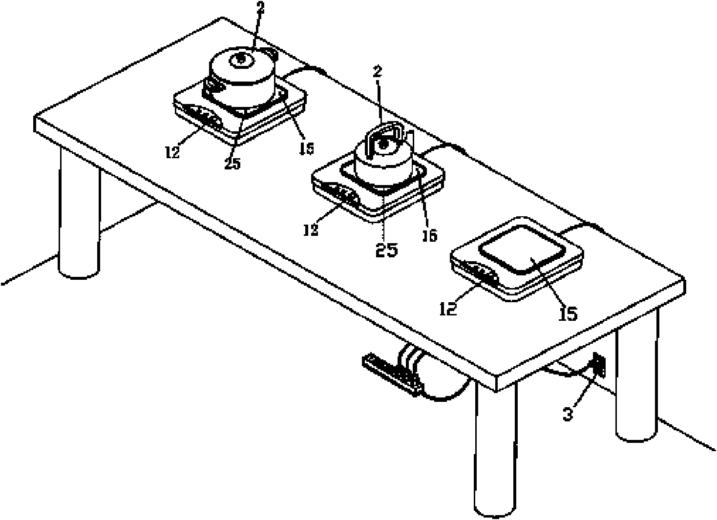
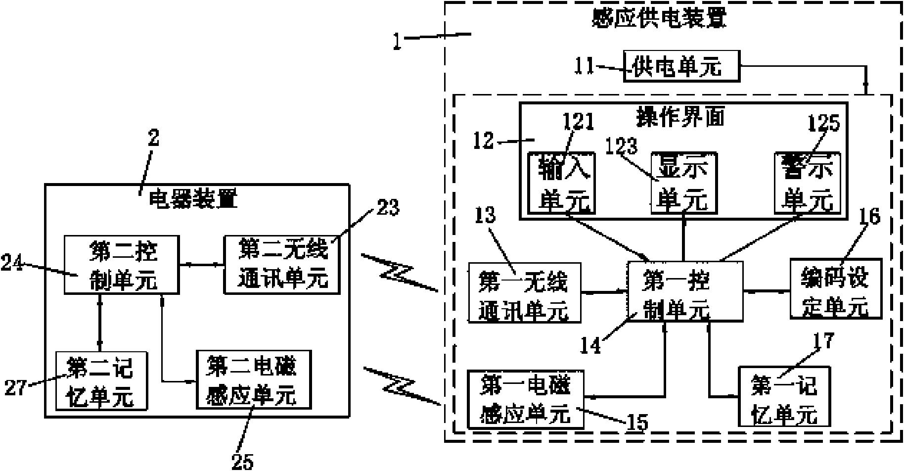
[0062] For a specific embodiment of the inductive power supply device disclosed by the present invention, please refer to figure 1 . The inductive power supply device 1 can supply power to a plurality of applicable inductive electrical devices 2 . When the applicable inductive electrical device 2 is placed on the working surface of the inductive power supply device 1, the first electromagnetic induction unit 15 of the inductive power supply device 1 will generate an electromagnetic field, so that the second electromagnetic induction unit 1 of the inductive electrical device 2 25 to obtain the induced current to...


PUM


Abstract

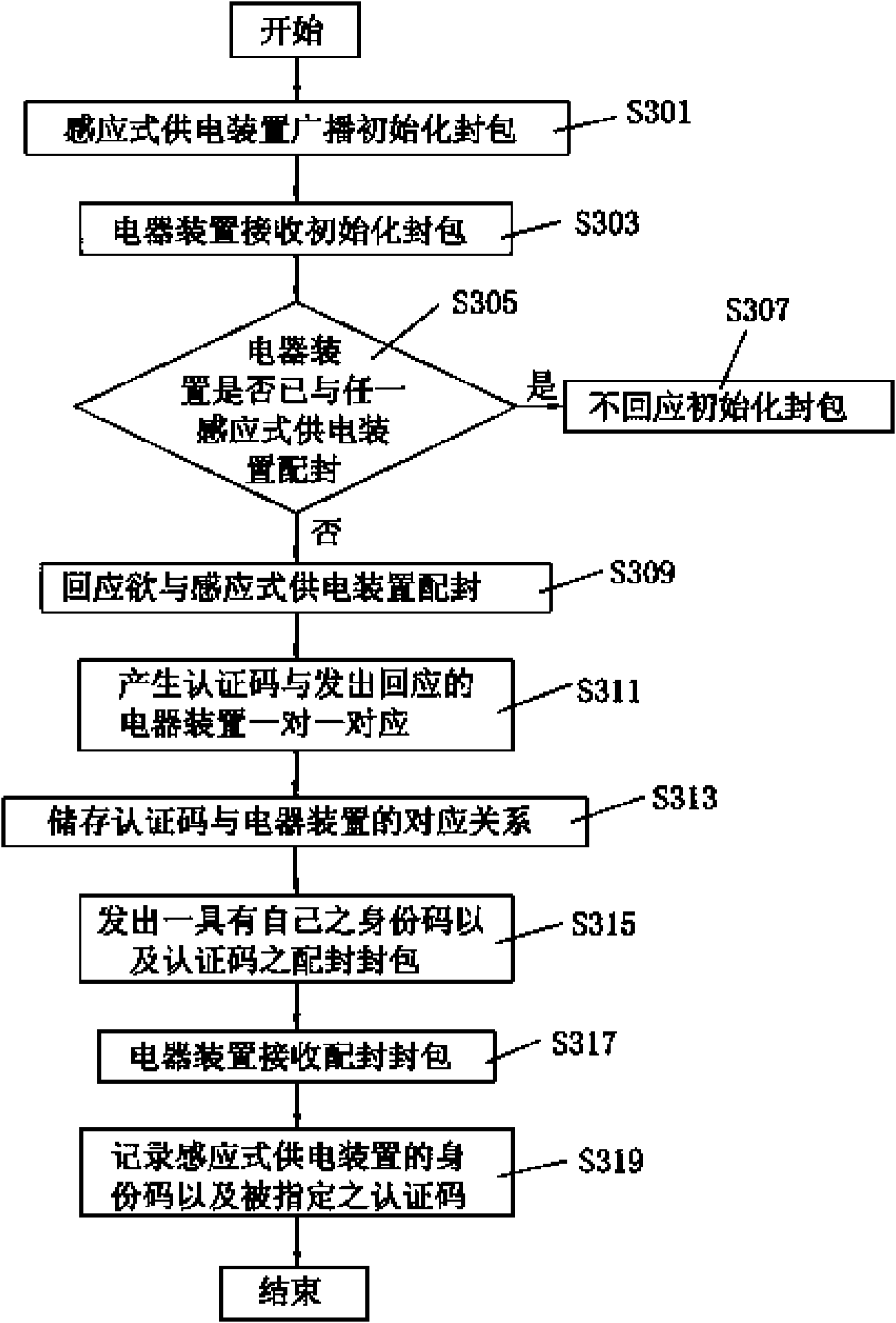
The invention relates to an inductive power supply device, an inductive power supply system and a control method of an inductive power supply system, which solves the problem that electric power specifications of power supply and power consumption are not matched during inductive power supply. The inductive power supply device is used for matching with at least one inductive electrical installation and comprises a code setting unit, a first wireless communication unit, a first electromagnetic inductive unit and a first control unit, wherein the code setting unit is used for specifying non-repeated authentication codes to each matched inductive electrical installation in one-to-one mode; the first wireless communication unit is used for information communication with each inductive electrical installation by wireless transmission; the first electromagnetic inductive unit is used for generating an electromagnetic field for inductive power supply; the first control unit is connected withthe code setting unit, the first wireless communication unit and the first electromagnetic inductive unit, and is used for controlling the first wireless communication unit to transmit the corresponding authentication codes to each matched inductive electrical installation; and the first control unit receives the authentication codes returned by each inductive electrical installation by the firstwireless communication unit so as to control the first electromagnetic inductive unit for supplying power to any inductive electrical installation with the matched authentication codes.

Description

technical field [0001] The invention relates to a power supply device for electromagnetic induction electrical appliances, a power supply system for electromagnetic induction electrical appliances and a control method for the power supply system for electromagnetic induction electrical appliances. Background technique [0002] In addition to being connected to the mains for operation, general electrical products mostly use battery packs. And the battery pack must be connected to the charger for charging every time it is used for a period of time. Since each electrical product requires different power consumption during operation, the specifications of battery packs and chargers are also different. Therefore, with the increase of electrical products in the home, various chargers are piled up at home, resulting in a shortage that is not easy to store. In order to reduce the use of battery packs and chargers, inductive power supply devices are gradually developed to provide p...

Claims


Application Information

Patent Timeline
Patent Type & Authority Applications(China)
IPC IPC(8): H02J17/00H02J50/10
Inventor 童士维张庐山李国良
Owner TSANN KUEN ZHANGZHOU ENTERPRISE CO LTD
Learn More