
Steam turbine having a cooling apparatus

A technology of steam and fluid machinery, which is applied in the direction of mechanical equipment, engine components, engine functions, etc., and can solve the problems that the internal shell cannot be adjusted and the actual conditions of the heat shield cannot be changed.

Inactive Publication Date: 2011-04-13
SIEMENS AG
View PDF7 Cites 0 Cited by
  • Summary
  • Abstract
  • Description
  • Claims
  • Application Information

AI Technical Summary

Problems solved by technology

[0005] The disadvantage here is that the actual conditions inside the heat shield can hardly be changed
This means that the actual conditions cannot be adjusted according to the requirements for the internal housing

Method used


Image

  • Steam turbine having a cooling apparatus
  • Steam turbine having a cooling apparatus
  • Steam turbine having a cooling apparatus

Examples


Embodiment Construction

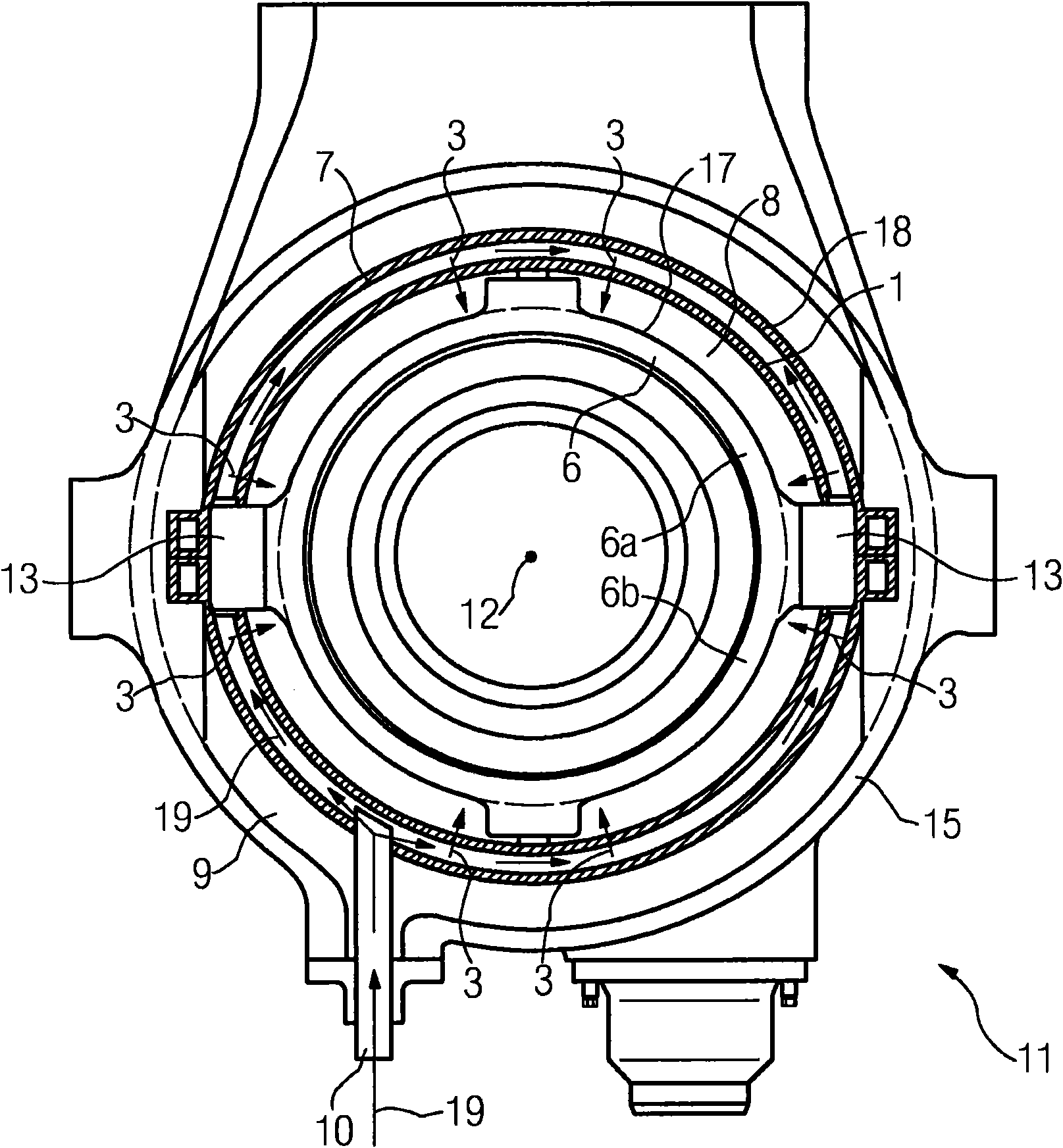
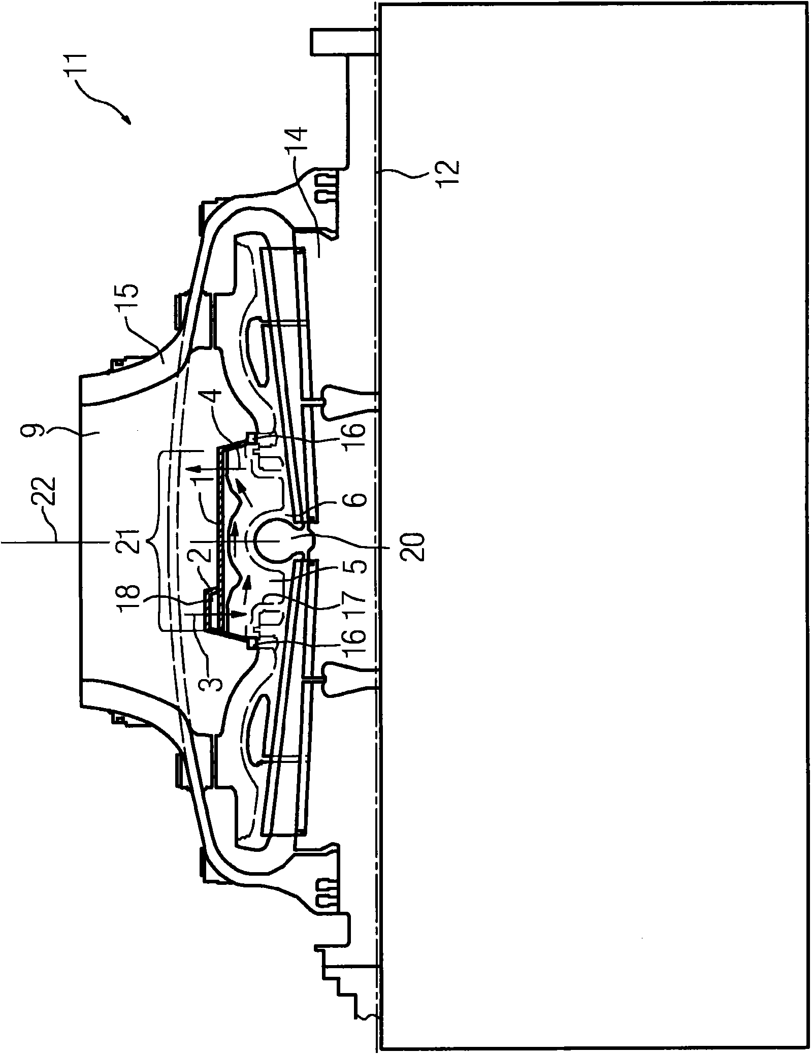
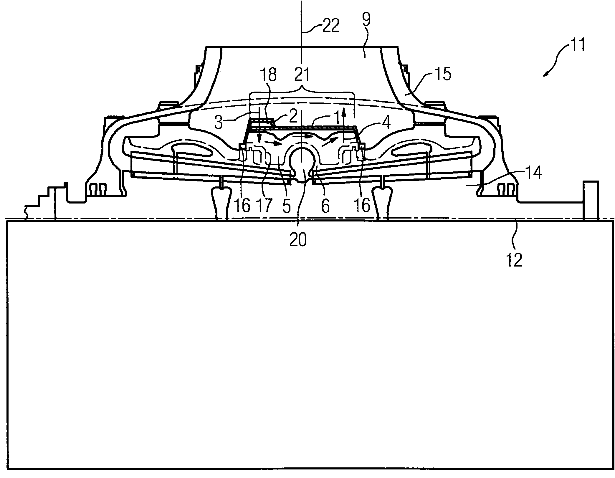
[0022] figure 1 A cross-sectional view along the axial direction of the medium-pressure part-turbine 11 is shown. The medium-pressure part-turbine 11 comprises an inner housing 6 that is substantially rotationally symmetrical about an axis of rotation 12 , wherein the inner housing 6 is composed of an upper inner housing part 6 a and an inner housing lower part 6 b . The inner housing upper part 6 a is connected to the inner housing lower part 6 b via a flange 13 and via screws, not shown in detail. For the sake of clarity, other components, such as the rotor 14, are not shown in detail.

[0023] An outer housing 15 is arranged around the inner housing 6 . In order to shield against heat, the housing 1 is arranged around the inner housing 6 . The outer casing 1 can be made of sheet steel and can be arranged on the inner housing 6 via a thermally movable seal 16 . During operation, intermediate-pressure waste steam is present in the waste steam chamber 9 , which has a signi...


PUM


Abstract

The invention relates to a turbomachine (11), comprising a rotor (14), an inner housing (6) which is arranged around the rotor (14), and an outer housing which is arranged around the inner housing (6), wherein an encapsulation (1) is arranged around the inner housing (6), wherein an annular channel (18) is arranged on said encapsulation (1), and steam flows via the annular channel (18) and holes (3) into a chamber (5) between the encapsulation (1) and the inner-housing outer surface (17), and flows out again via holes (4) which are situated in the encapsulation (1).

Description

technical field [0001] The invention relates to a fluid machine comprising a rotor, an inner housing arranged around the rotor and an outer housing arranged around the inner housing, wherein a hermetically closed housing is arranged around the region of the inner housing. Background technique [0002] In this case, a fluid machine is to be understood in particular as a steam turbine. Steam turbines are classified into so-called high-pressure part-turbines, medium-pressure part-turbines or low-pressure part-turbines. At present there is no uniform division of steam turbines into the aforementioned sub-turbines. The high-pressure section turbine is usually charged with steam at a temperature of up to 620° C. and a pressure of up to 350 bar. The steam emerging from the high-pressure part-turbine is reheated in an intermediate heater to a temperature of up to 620° C. and then flows into the intermediate-pressure part-turbine, from which the steam then flows into the low-pressu...

Claims


Application Information

Patent Timeline
Patent Type & Authority Applications(China)
IPC IPC(8): F01D25/24F01D25/26
CPCF05D2260/205F01D25/26F05B2220/301F05B2260/233F05D2220/31F05B2260/205F05D2260/2322
Inventor A·乌尔马
Owner SIEMENS AG
Learn More