Magneto-resistive sensor for measuring magnetic fields

a magnetic field and resistive sensor technology, applied in the direction of magnetic field magnitude/direction, measurement devices, instruments, etc., can solve the problems of disadvantageous reduction of the resistance value of the magneto-resistive strip to approximately one-third, insufficient linearity and temperature independence of the described circuit, etc., to achieve convenient rotation, double the sensor sensitivity, and easy rotation

Active Publication Date: 2012-10-18
MEAS DEUTLAND
View PDF4 Cites 14 Cited by
  • Summary
  • Abstract
  • Description
  • Claims
  • Application Information

AI Technical Summary

Benefits of technology

[0013]Spin-valve systems have proven advantageous when using GMR layer systems for the linearized and temperature-stabilized magneto-resistive sensor. These include, referring to FIG. 10, a pinned ferromagnetic layer 20 with a direction of magnetization which is defined by the immediate adjacency of a natural or artificial antiferromagnetic layer and which cannot be noticeably influenced by the magnetic field strengths to be measured. They further include a free ferromagnetic layer 21, the magnetization of which can be easily rotated by external magnetic fields, and a non-magnetic intermediate layer 22 with a layer thickness selected so as to almost decouple the magnetization of the two ferromagnetic layers. The resistance value of the spin valve layer systems is at a minimum when the magnetizations of the two ferromagnetic layers are parallel, and at a maximum when they are antiparallel. If the magnetization of the pinned layer is adjusted to lie in the longitudinal direction of the strips and if the magnetization of the free layer is oriented in the same direction without external field due to the effect of the shape anisotropy, then the resistance value of the layer system increases with the square of the field strength for an external field perpendicular to longitudinal direction. Accordingly, the characteristic curve can therefore be linearized by employing the same means as for AMR sensors, i.e., by connecting the layer strips 24 with different shape anisotropy, in series. The shape anisotropy can be adjusted, for example, by suitable selection of the widths of the layer strips. By adjusting the magnetization of the layer strips of the resistors of each half bridge 25, 26 in opposite directions, both resistors then change in the opposite direction in a magnetic field. This doubles the sensor sensitivity. The same concept also applies for a full bridge where the diagonally opposing resistors have the same direction of magnetization of the pinned layer. The thickness of the non-magnetic intermediate layer of the spin-valve systems can be selected so that the two ferromagnetic layers have a slight ferromagnetic or antiferromagnetic coupling. The magnetization of the free layer can still easily rotate. The stability of the magnetization of the free layer increases significantly in the presence of interfering fields. The constancy of the slope of the linearized characteristic curve is similarly improved, as for AMR sensors, by applying a stabilizing field in the longitudinal direction of the strips.
[0014]The coupling field strengths may be different for different layer strips, as illustrated in FIG. 11, where magneto-resistive layer strips 6 and 7 of FIG. 1 are shown in cross-section on substrate 19; magneto-resistive layer strip 6 has ferromagnetic layers 20, 21 and non-magnetic intermediate layer 22, while magneto-resistive layer strip 7 has ferromagnetic layers 20′, 21′ and non-magnetic intermediate layer 22′ of a different thickness from that of non-magnetic intermediate layer 22 of strip 6, thereby providing different coupling field strengths.
[0015]To realize stable sensor signals with changing temperature in a defined magnetic field to be measured by the series connection of magnetic field-independent layer resistors with negative temperature coefficient according to the invention when using the magneto-resistive layer strips, layer strips with a resistance value of approximately 1% of the resistance value of the magneto-resistive layer strips are adequate. The resulting decrease of the sensor signal compared to a sensor signal that is not thermally stabilized it is therefore negligible. The zero offset of the sensor bridge can be easily compensated with AMR sensors, if the resistance of the two bridge resistors that are not affected by the magnetic field is initially by approximately 1 ppm above that of the field-dependent resistors. The zero offset of the sensor bridge and the region of the characteristic curve which has the best temperature stabilization can be adjusted separately, if adjustment ranges are provided for both the magneto-resistive layer as well as the additional layer with negative temperature coefficient of the resistance value.

Problems solved by technology

Sensors of the aforedescribed type are known in the art, however, their linearity and temperature independence are not adequate for the applications.
However, the described circuit is complex and too expensive for many applications.
In sensors where the characteristic curve is linearized by inclining the conductive layer strips on the magneto-resistive strips, the conductive layer strips disadvantageously lower the resistance values of the magneto-resistive strips to approximately one-third.
This necessitates an increase of the sensor area by approximately the same factor, which is not economical.
This is technologically very challenging.
The aforementioned method for linearization can only be applied to AMR sensors because it is based on a change in the current direction in the resistive strips.
Both approaches disadvantageously require complex electronic circuitry and are difficult to adjust.
This attempt, however, only prevents a common-mode offset at a different temperature.
However, it would be a mistake to conclude that the signal of the sensor corresponding to the applied magnetic field is also the same at all temperatures.

Method used


Image

  • Magneto-resistive sensor for measuring magnetic fields
  • Magneto-resistive sensor for measuring magnetic fields
  • Magneto-resistive sensor for measuring magnetic fields

Examples


Embodiment Construction

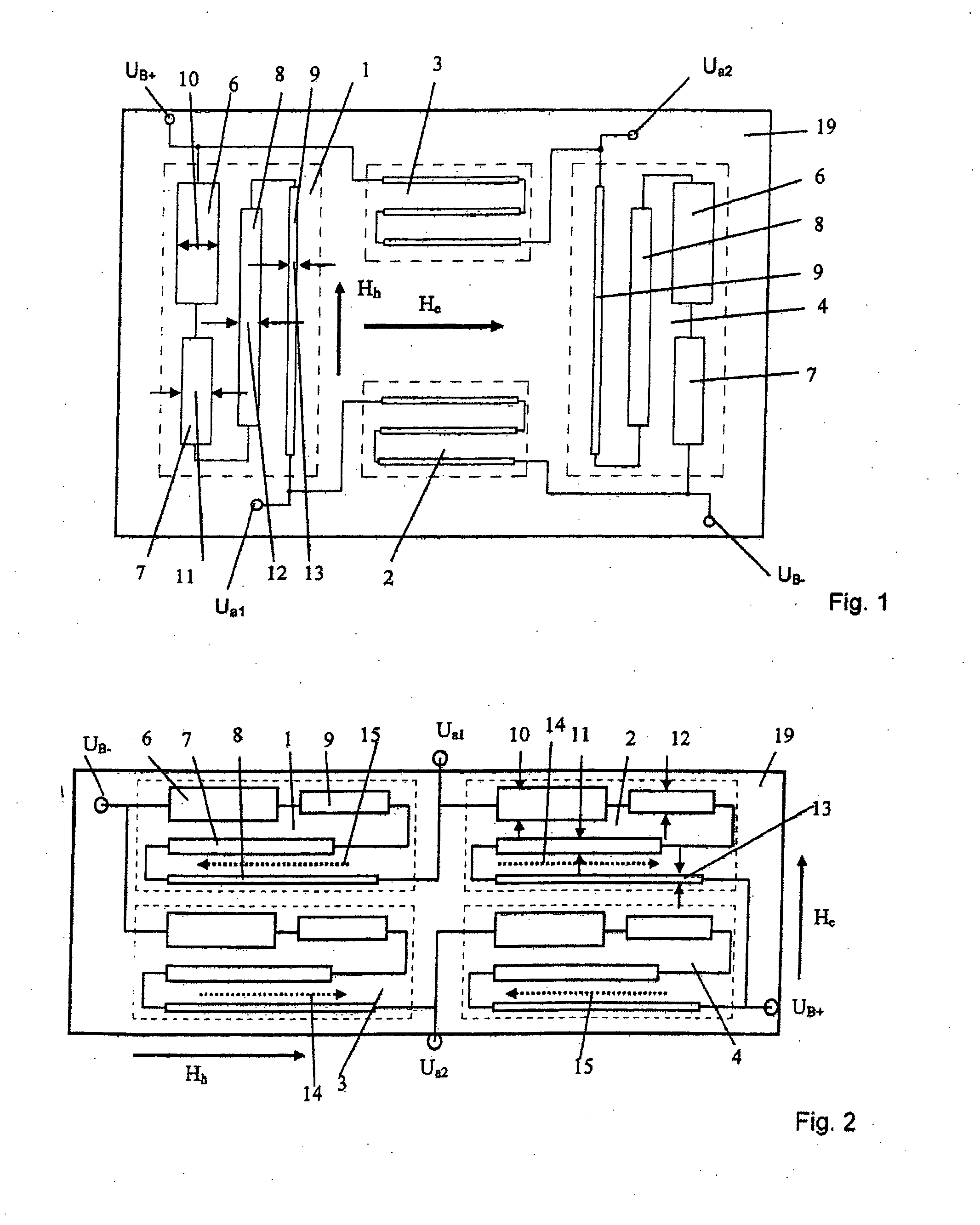
[0028]FIG. 1 shows a magneto-resistive sensor bridge according to the invention with resistors 1; 2; 3; 4 constructed of AMR layer strips and disposed on a substrate 19. The resistors 1; 2; 3; and 4 are each enclosed by dashed lines. The operating voltage is applied to the bridge between the terminals UB+ and UB−. The output signal of the bridge is measured as a voltage difference between Ua2 and Ua1. The resistors 1 and 4, which are diagonally opposed in the electric circuit of the bridge (see FIG. 8) each include four AMR layer strips 6; 7; 8; 9. These AMR layer strips 6; 7; 8; 9 have parallel longitudinal strip directions, different shape anisotropies and different lengths and are in the depicted diagram arranged mirror-symmetric to the two resistors 1 and 4. The different shape anisotropy of the AMR layer strips 6; 7; 8; 9 is adjusted in FIG. 1 by selecting different widths 10; 11; 12; 13. Because the AMR layer strips 6; 7; 8; and 9 designated with the same reference symbol have...


PUM


Abstract

Magneto-resistive sensors based on the AMR or GMR effect exhibit substantially enlarged linear characteristic curve regions as a result of the fact that their resistances are composed of magneto-resistive layer strips of differing anisotropic forms. Differing anisotropic forms can be achieved by different strip widths, strip thicknesses, strip intervals or strip materials. The temperature compensation for the output voltage of the magneto-resistive sensors, at least at one point on the characteristic curve, is achieved by the series connection of an additional layer strip with a temperature coefficient that differs from that of the magneto-resistive material to at least one magneto-resistive resistance of the sensor.

Description

CROSS-REFERENCE TO RELATED APPLICATIONS[0001]This application is a divisional application of co-pending U.S. patent application Ser. No. 10 / 572,009 entitled Magneto-Resistive Sensor for Measuring a Magnetic Field Based on an Anisotropic Magneto-Resistive (AMR) Effect or a Gigantic Magneto-Resistive (GMR) Effect, filed Apr. 17, 2008, which is the U.S. national stage of Intl Application No. PCT / EP2004 / 010192, filed Sep. 13, 2004, which claims priority benefit of German Application No. 10 42 260.9, filed Sep. 11, 2003, the entire contents of all of which are herein incorporated by reference for all purposes.BACKGROUND OF THE INVENTION[0002]The invention is directed to sensors which employ either the anisotropic magneto-resistive effect (AMR) or the gigantic magneto-resistive effect (GMR) and are suitable for indicating magnetic fields. In particular, the sensor elements improved by the invention are employed for automatically identifying when a characteristic value is exceeded. For exa...

Claims


Application Information

Patent Timeline
Patent Type & Authority Applications(United States)
IPC IPC(8): G01R33/09
CPCG01R33/09G01R33/05
Inventor BARTOS, AXELMEISENBERG, ARMINDETTMANN, FRITZ
Owner MEAS DEUTLAND
Why Eureka
Try Eureka