Multifuel internal-combustion engine

An internal combustion engine and multi-fuel technology, which is applied to liquid fuel feeders, internal combustion piston engines, combustion engines, etc., can solve the problems of increased PM and smoke generation, and achieve suppression of noise, suppression of thermal efficiency deterioration, and suppression of torque The effect of the change

Inactive Publication Date: 2013-12-11
TOYOTA JIDOSHA KK
View PDF3 Cites 0 Cited by
  • Summary
  • Abstract
  • Description
  • Claims
  • Application Information

AI Technical Summary

Problems solved by technology

However, when performing compression self-ignition diffusion combustion using fuel with low compression ignitability, it is not preferable because the amount of PM and smoke generated will increase by delaying the fuel injection timing.

Method used


Image

  • Multifuel internal-combustion engine
  • Multifuel internal-combustion engine
  • Multifuel internal-combustion engine

Examples


Embodiment 1

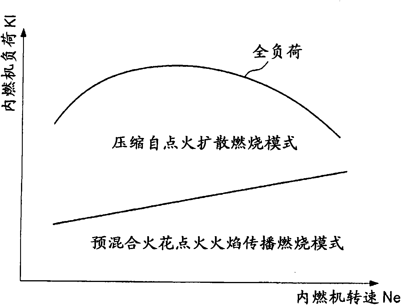
[0066] Below, according to Figure 1 to Figure 7 Embodiment 1 of the multi-fuel internal combustion engine according to the present invention will be described. The multi-fuel internal combustion engine is an internal combustion engine that operates by introducing at least one fuel of at least two fuels having different properties into a combustion chamber, or introducing a mixed fuel composed of the at least two fuels into the combustion chamber. In this embodiment, the latter multi-fuel internal combustion engine is taken as an example for description.

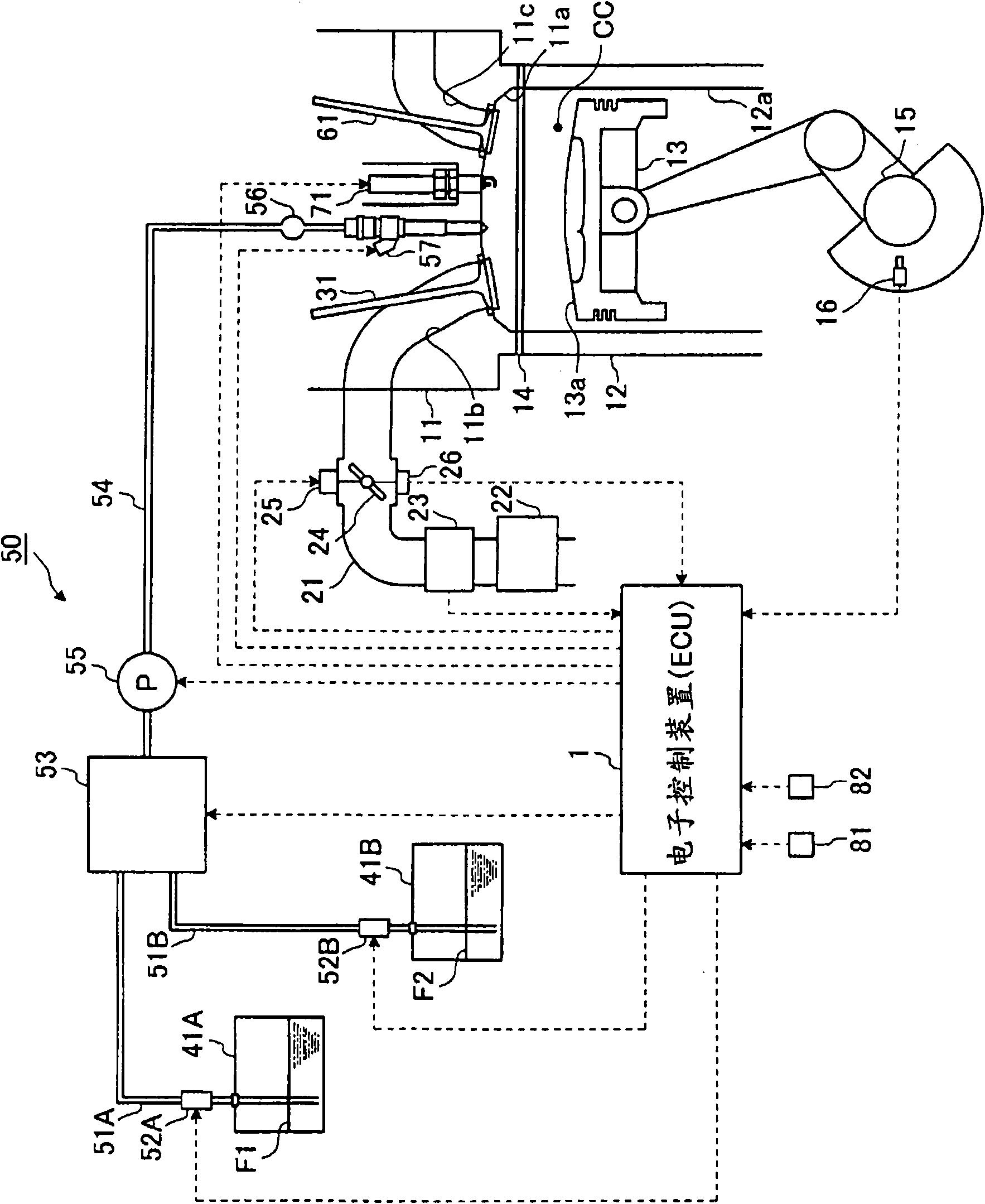
[0067] This multi-fuel internal combustion engine, with figure 1 The illustrated electronic control unit (ECU) 1 performs various control operations such as combustion control. This electronic control device 1 is composed of a CPU (Central Processing Unit) not shown in the figure, a ROM (ReadOnly Memory) in which predetermined control programs, etc. are stored in advance, and a RAM (Random Access Memory: random access mem...

Embodiment 2

[0137] Second, according to Figure 8 and Figure 9 Embodiment 2 of the multi-fuel internal combustion engine according to the present invention will be described.

[0138] Generally, if the in-cylinder pressure in the combustion chamber CC can be detected, the ignition timing of the pre-injected fuel or the increase rate of the in-cylinder pressure can be grasped from the change in the pressure. Thus, in the multi-fuel internal combustion engine of Embodiment 1 described above, in a case where the in-cylinder pressure can be detected or estimated, it can be judged whether or not the pre-injected fuel is undergoing rapid combustion. In addition, the larger the pre-injection amount FP, the higher the cylinder pressure, and the increase rate of the cylinder pressure due to the pre-injection can be reversed to calculate the pre-injection amount FP. Therefore, by feeding back the increase rate of the in-cylinder pressure at the time of the next pre-injection, even if the Figur...

Embodiment 3

[0159] Second, based on Figure 10 Embodiment 3 of the multi-fuel internal combustion engine according to the present invention will be described.

[0160] In each of the above-mentioned Embodiments 1 and 2, an example of a so-called direct-injection multi-fuel internal combustion engine in which the mixed fuel of the first fuel F1 and the second fuel F2 is directly injected into the combustion chamber CC was exemplified. However, this Embodiment 3 exemplifies a multi-fuel internal combustion engine in which this mixed fuel is injected not only into the combustion chamber CC but also into the intake port 11b.

[0161] For example, this kind of multi-fuel internal combustion engine can be replaced by the fuel supply device 50 in the multi-fuel internal combustion engine of each embodiment 1, 2 Figure 10 The fuel supply device 150 shown is constructed. In addition, the Figure 10 The case based on the multi-fuel internal combustion engine of the first embodiment is exemplifi...


PUM


Abstract

To improve an ignitability to a fuel having a low compressed ignitability in a combustion chamber (CC) in a compressed self-ignition diffusive combustion mode operation. In a multi-fuel internal combustion engine operated by introducing at least one type of fuel among at least two types of fuels (F1, F2) having different properties into a combustion chamber (CC) or introducing a mixed fuel composed of at least the two types of fuels (F1, F2) into the combustion chamber (CC), an electronic control unit (1) is provided with a fuel characteristics detection means that detects an ignitability index value as an index showing a compressed ignitability of a fuel itself introduced into the combustion chamber (CC), and a fuel injection control means that previously injects, when a compressed self-ignition diffusive combustion is performed using a fuel in the combustion chamber, which is determined to have a low compressed ignitability based on the ignitability index value, the fuel at a predetermined timing in a period from an intake stroke to a compression stroke, and thereafter mainly injects the fuel and introduces the fuel having the low compressed ignitability into the combustion chamber (CC).

Description

technical field [0001] The present invention relates to a multi-fuel internal combustion engine. The multi-fuel internal combustion engine operates by introducing at least one fuel of at least two fuels with different properties into a combustion chamber, or introducing a mixed fuel composed of the at least two fuels into a combustion chamber. run. Background technique [0002] In the past, a so-called multi-fuel internal combustion engine that operates on a plurality of fuels with different properties has been known. For example, in Patent Document 1 described below, a multi-fuel internal combustion engine is disclosed that injects low-octane fuel into a mixture of high-octane fuel injected by an intake pump to The self-ignition of the low-octane fuel serves as a starting point, and the flame-propagation combustion of the high-octane fuel mixture can thereby increase the combustion speed and shorten the time until the combustion is completed, so knocking can be prevented. ...

Claims


Application Information

Patent Timeline
Patent Type & Authority Patents(China)
IPC IPC(8): F02D41/38F02D41/40F02D45/00
CPCY02T10/123F02D19/061Y02T10/36F02D13/0226F02D41/0025F02D35/021F02D41/3076F02M37/0064F02B3/06F02D19/0636F02D41/401F02D19/0649Y02T10/44F02B17/005F02D2200/0408F02D35/023F02B2275/16F02D19/0689F02D2200/0414F02D2200/0611F02D2200/0612F02B23/101F02B2075/125F02D35/028F02D19/0692F02D19/081F02D19/0665F02M37/0088F02D41/403F02D19/0694Y02T10/12Y02T10/30Y02T10/40
Inventor 丹野史朗伊藤泰志
Owner TOYOTA JIDOSHA KK
Why Eureka
Try Eureka