Automatic capping machine

A capping machine, automatic technology, applied to bottle/container caps, capping containers tightly with caps, bottle filling, etc., can solve the problems of slow packaging speed, leaky packaging, waste of human resources, etc., and reduce the defective rate of capping , Capping position is accurate, and the effect of capping efficiency is improved

Inactive Publication Date: 2011-04-20
苏州澳昆智能机器人技术有限公司
View PDF0 Cites 15 Cited by
  • Summary
  • Abstract
  • Description
  • Claims
  • Application Information

AI Technical Summary

Problems solved by technology

[0002] At present, many cup lids in the food industry, especially some plastic light-weight cup lids, are difficult to automatically seal by machines, mainly by manual sealing, which wastes human resources on the one hand, and the packaging speed is slow and the packaging quality is uneven. , there are often phenomena such as leaked packaging, inadequate packaging or man-made damage, which has brought huge troubles to the current food processing industry

Method used


Image

  • Automatic capping machine
  • Automatic capping machine
  • Automatic capping machine

Examples


Embodiment

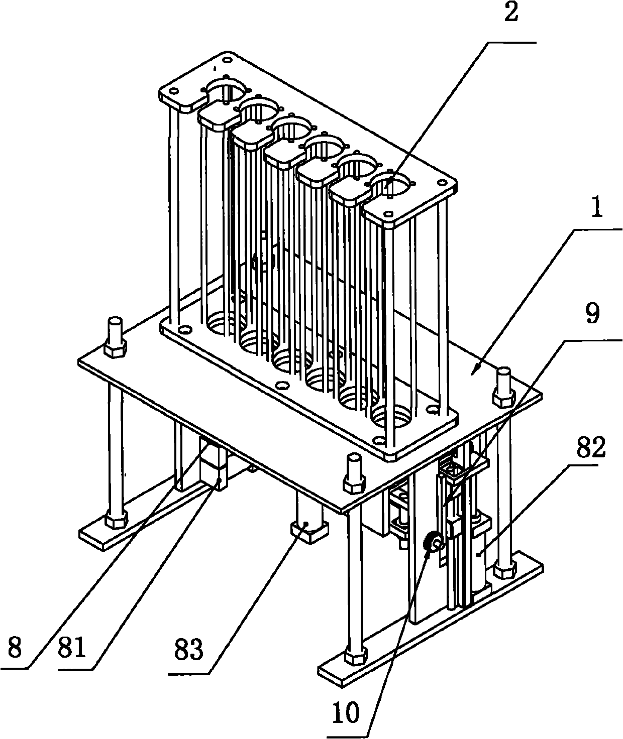
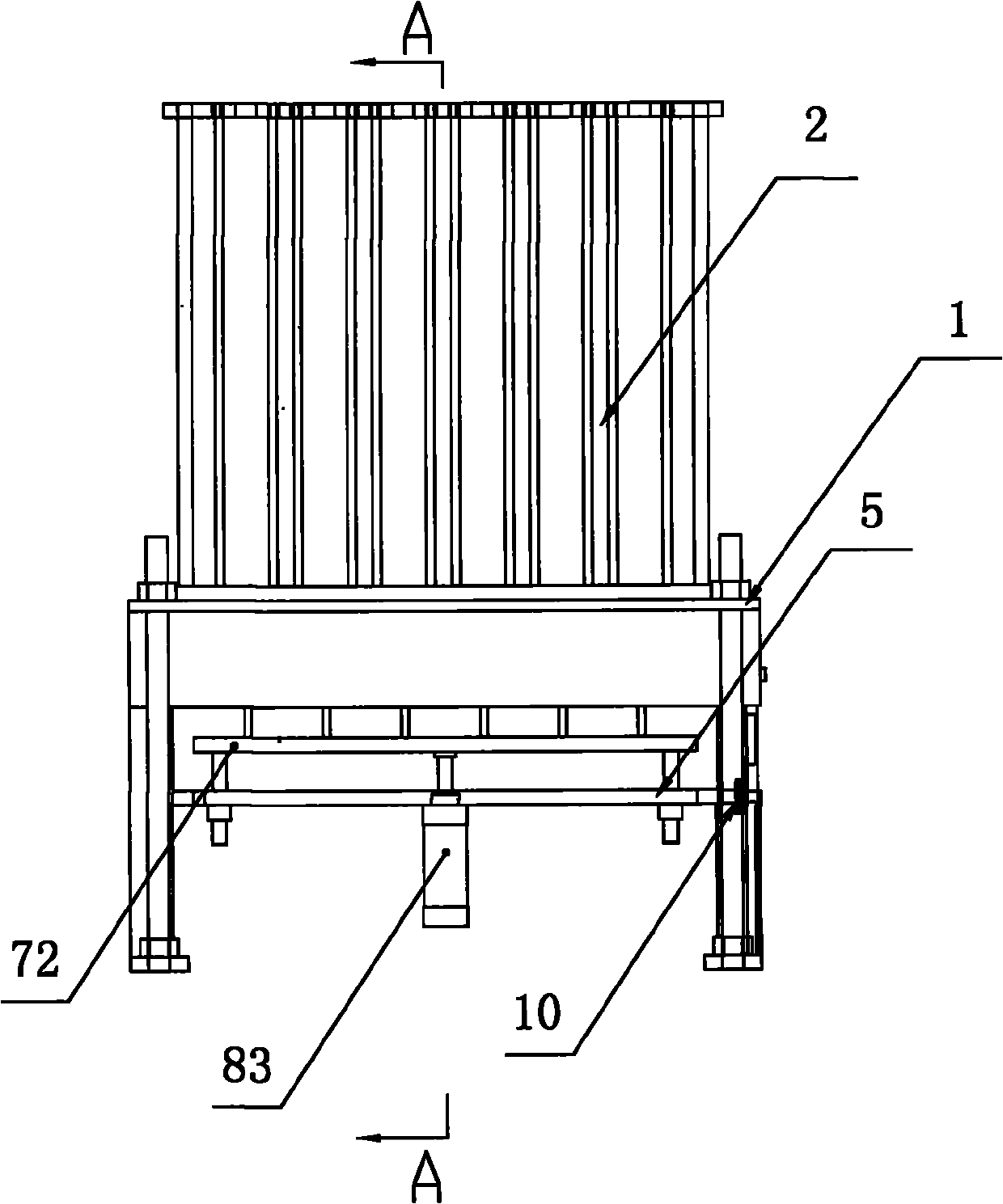
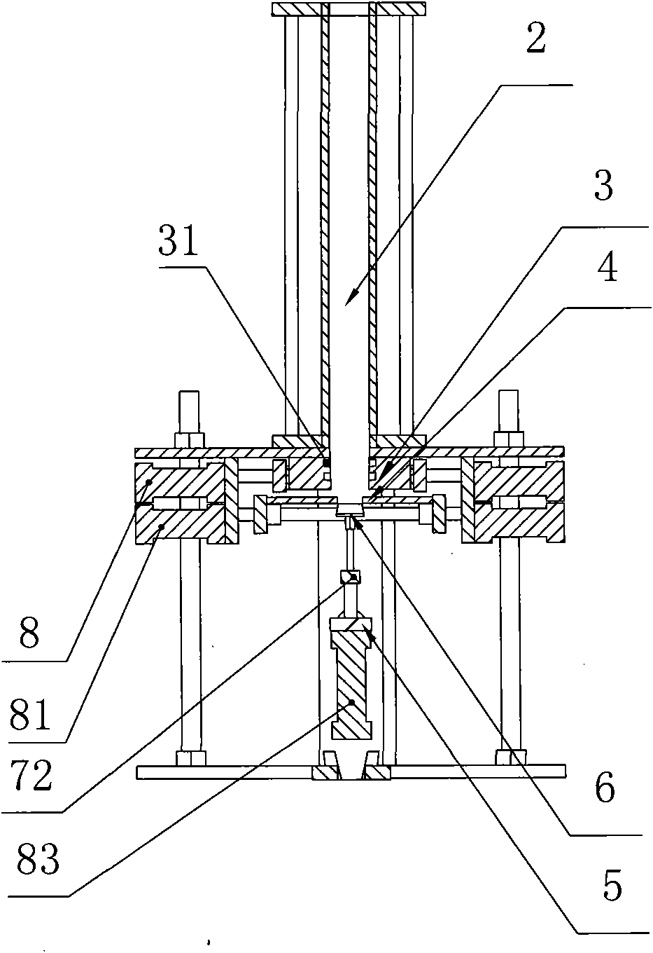
[0019] Embodiment: an automatic capping machine, including a frame 1, a placement channel 2, a first chuck 3, a second chuck 4, a suction cup holder 5 and a suction cup 6, based on the direction of use, at least one longitudinal direction has a setting The height of the placement channel 2 is fixed on the top of the frame 1, and the inside of the placement channel 2 can accommodate several axially overlapping cup covers. The cup covers can slide longitudinally along the placement channel 2. The initial state of the disk 3 is an open state, the first chuck is radially retractable and axially stopped and positioned on the frame 1 at the lower end of the placement channel 2, and the initial state of the second chuck 4 that is consistent with the number of placement channels 2 is a contracted state , the second chuck can be radially opened and the axial stopper is positioned on the frame 1 at a set distance below the first chuck 3, and the axis lines of the first and second chucks ...


PUM


Abstract

The invention discloses an automatic capping machine. At least one placement channel is fixedly reserved above a rack; the initial states of a first chunk plate and a second chunk plate are respectively an open state and a retraction state; the first chunk plate and the second chunk plate are placed under the placement channel at an upper position and a lower position in the axial direction; the first chunk plate and the second chunk plate are radially positioned on the rack in a retractable way and an openable way respectively; the inner wall of the first chunk plate is provided with at least one circle of annular groove; when the first chunk plate and the second chunk plate are in the open state, the inside diameters of the first chunk plate and the second chunk plate are both greater than the maximal outside diameter of a cup cover; when the first chunk plate is in the retraction state, the edge at the upper end of the cup cover is clamped in the annular groove inside the edge; when the second chunk plate is in the retraction state, the inside diameter of the second chunk plate is less than the outside diameter of the lower end of the cup cover; a suction cup frame is fixedly positioned on the rack in a radial direction rotatably and axially; suction cups in the same number of the placement channels are vertically positioned on the radial outside wall of the suction cup frame telescopically; and when the suction cups are positioned at the upper end of the suction cup frame, the suction cups are exactly positioned on the lower side of the inside diameter of the second chunk plate completely. The automatic capping machine has a simple structure, high work efficiency and low encapsulation defective rate, and is convenient to operate and reliable in use.

Description

technical field [0001] The invention relates to a cup capping device, in particular to an automatic capping machine. Background technique [0002] At present, many cup lids in the food industry, especially some plastic light cup lids, are difficult to automatically seal by machines, mainly manually, which wastes human resources on the one hand, and the packaging speed is slow and the packaging quality is uneven. , Leaky packaging, inadequate packaging or man-made damage often occur, which has brought huge troubles to the current food processing industry. Contents of the invention [0003] In order to overcome the above defects, the present invention provides an automatic capping machine, which can quickly and accurately seal the cup lid on the cup. [0004] The technical solution adopted by the present invention in order to solve its technical problems: an automatic capping machine, including a frame, a placement channel, a first chuck, a second chuck, a suction cup frame...

Claims


Application Information

Patent Timeline
Patent Type & Authority Applications(China)
IPC IPC(8): B67B3/00
Inventor 李政德刘霞
Owner 苏州澳昆智能机器人技术有限公司
Why Eureka
Try Eureka