Improvement method for capacitive touch pad edge positioning

A capacitive touch, board edge technology, applied in electrical digital data processing, data processing input/output process, instruments, etc., to achieve the effect of eliminating dead space

Inactive Publication Date: 2011-04-20
ELAN MICROELECTRONICS CORPORATION
View PDF4 Cites 12 Cited by
  • Summary
  • Abstract
  • Description
  • Claims
  • Application Information

AI Technical Summary

Problems solved by technology

[0005] Therefore, there are above-mentioned inco

Method used


Image

  • Improvement method for capacitive touch pad edge positioning
  • Improvement method for capacitive touch pad edge positioning
  • Improvement method for capacitive touch pad edge positioning

Examples


Embodiment Construction

[0022] The present invention will be further described below in conjunction with embodiment and accompanying drawing.

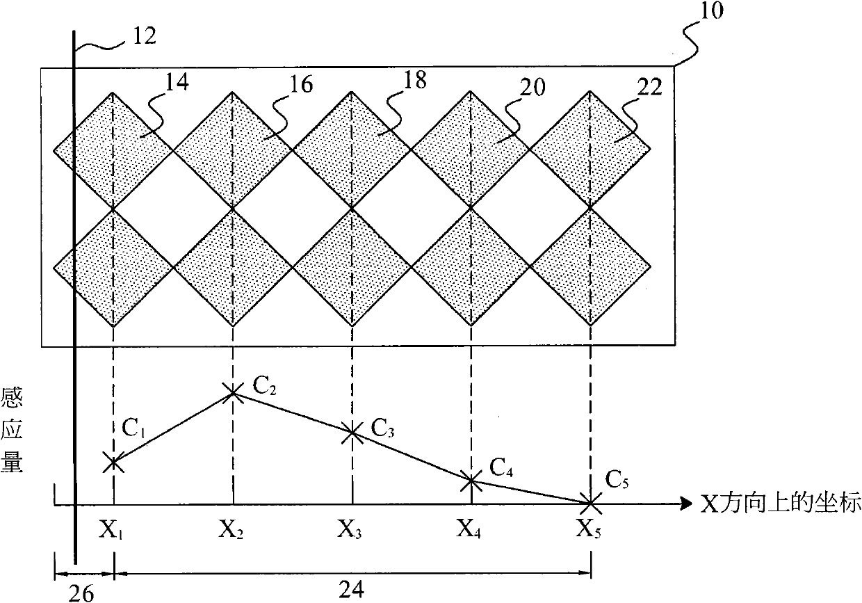
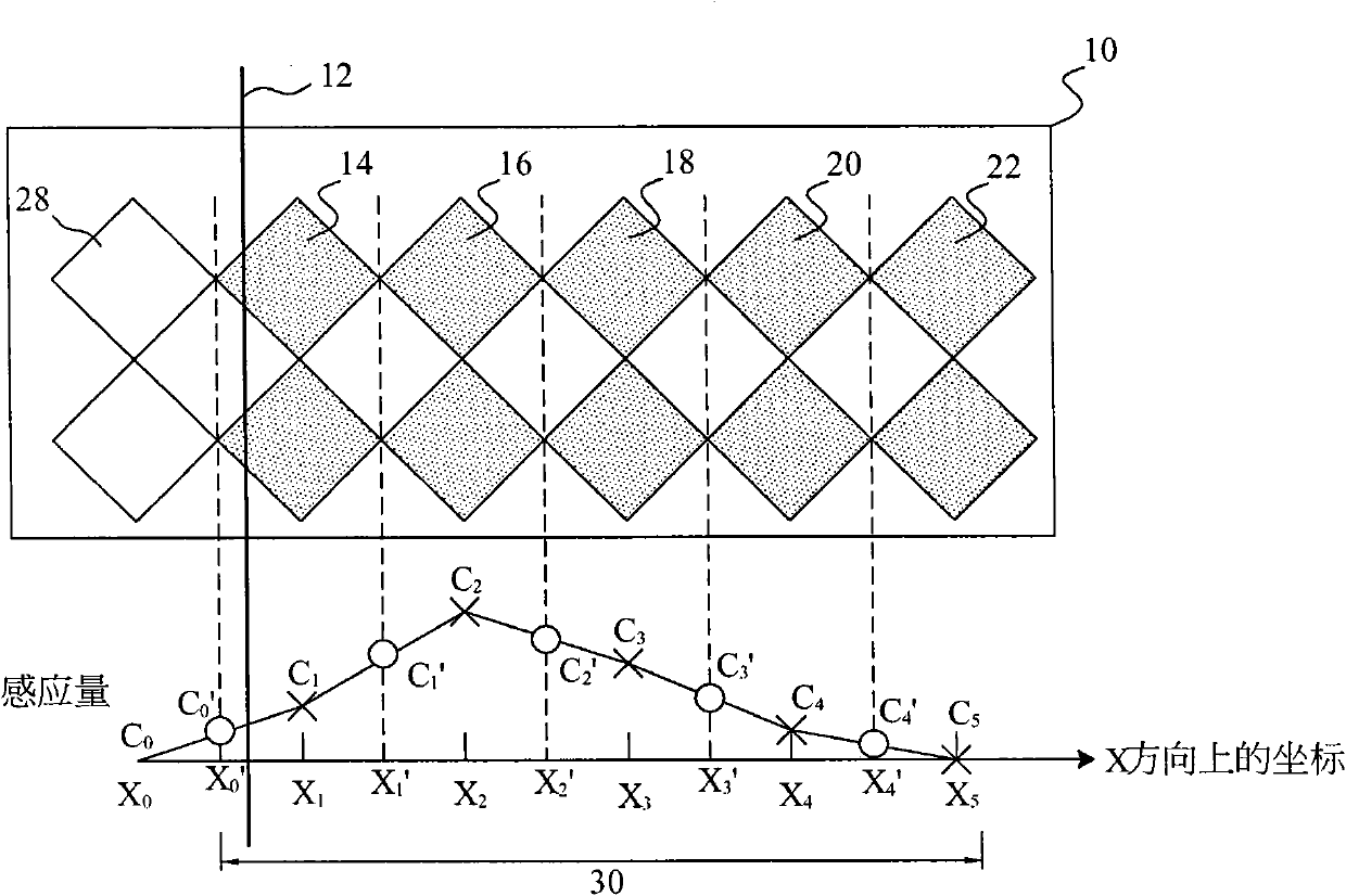
[0023] see now figure 2 , figure 2 It is a schematic diagram of the positioning method of the capacitive touch panel of the present invention. As shown in the figure, a virtual sensing line 28 in the X direction is defined outside the edge sensing line 14 of the capacitive touch panel 10, and a virtual coordinate X is given. 0 . When an object is touched, the capacitance value of the touched physical sensing line will change, and the capacitance value of each sensing line 14, 16, 18, 20, and 22 will be converted by a converter (not shown in the figure) to produce different values Inductive value C m , while the virtual induction line 28 gives the virtual induction value C 0 , which is preset to 0 in this embodiment. In order to locate the coordinate X of the object, first obtain the intermediate value X' of the coordinates of any two adjacent inductio...


PUM


Abstract

The present invention relates to an improvement method for capacitive touch pad edge positioning, the capacitive touch pad possesses a plurality of tangible induction lines in one direction; one of the plurality of tangible induction lines is an edge induction line; the plurality of tangible induction lines possess respective coordinates; the method is characterized by comprising following steps: obtaining induction amounts of the plurality of tangible induction lines; defining virtual induction lines at the external sides of the edge induction lines, and giving virtual coordinates and virtual induction amounts to the virtual induction lines; calculating average induction amounts of two random adjacent induction lines and coordinate medians of the plurality of tangible induction lines and the plurality of virtual induction lines; determining the coordinate in the direction by interpolation operation of the average induction amounts and the coordinate medians. The improvement method for capacitive touch pad edge positioning provided by the invention has the advantages in that blind angle regions can be eliminated.

Description

technical field [0001] The invention relates to a capacitive touch panel, in particular to a method for improving edge positioning of the capacitive touch panel. Background technique [0002] Such as figure 1 As shown, the capacitive touch panel 10 has a plurality of sensing lines 14, 16, 18, 20 and 22 in the X direction from its edge 12 to the right, and the center position of each sensing line is its coordinate X m , coordinate X m Can be relative coordinates or absolute coordinates. When an object is touched, the capacitance value of the touched sensing line will change, and the capacitance value of each sensing line 14, 16, 18, 20, and 22 will be converted by a converter (not shown in the figure) to produce different values ​​of sensing Quantity C m , from the coordinates X of each induction line 14, 16, 18, 20 and 22 m and its inductance C m Inner difference operation, locate the coordinates of the object [0003] X = Σ ...

Claims


Application Information

Patent Timeline
IPC IPC(8): G06F3/044
Inventor 粘紘陶逸欣邓智先蔡欣学黄俊中林嘉兴
Owner ELAN MICROELECTRONICS CORPORATION
Why Eureka
Try Eureka