Narrow-linewidth laser

A laser and narrow linewidth technology, which is applied to lasers, laser components, semiconductor lasers, etc., can solve the problems of poor system stability and large volume, and achieve the effect of realizing frequency, narrow linewidth and high power output

Inactive Publication Date: 2011-04-20
NAT INST OF METROLOGY CHINA
View PDF1 Cites 16 Cited by
  • Summary
  • Abstract
  • Description
  • Claims
  • Application Information

AI Technical Summary

Problems solved by technology

[0008] However, Sandra Stry et al. used Littrow and Littman structure to form a high-power external cavity laser with a relatively wide linewidth; Yabai He and Brian J.Orr proposed to use discrete components to fold the F-P cavity, and the F-P cavity of the discrete component is susceptible to external audio and mechanical vibrations The interference and influence of temperature and temperature changes, the volume of the cavity is relatively large, and the stability of the system is relatively poor

Method used


Image

  • Narrow-linewidth laser
  • Narrow-linewidth laser
  • Narrow-linewidth laser

Examples


Embodiment Construction

[0044] In order to make the object, technical solution and advantages of the present invention clearer, the present invention will be described in further detail below in conjunction with specific embodiments and with reference to the accompanying drawings.

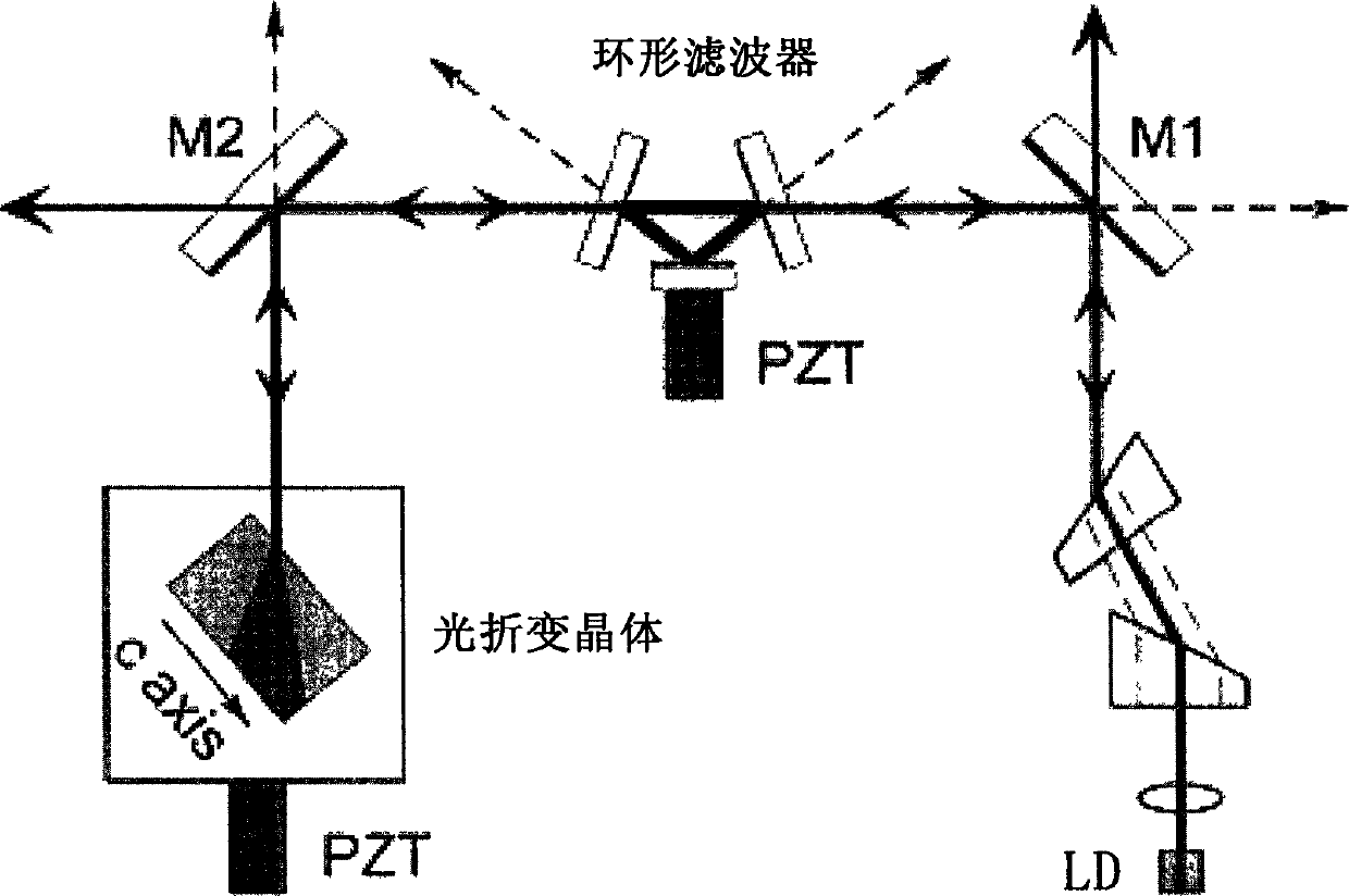
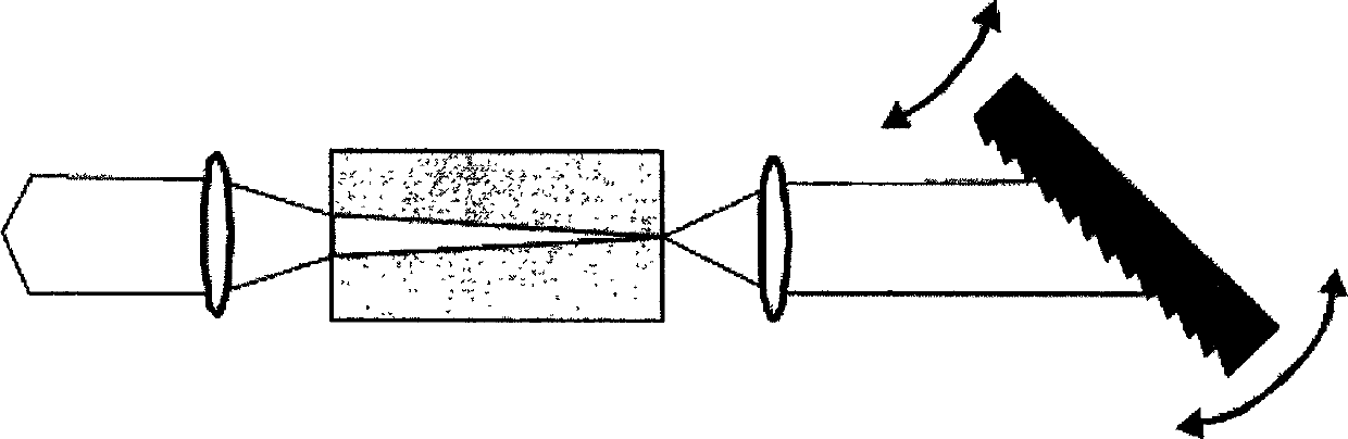
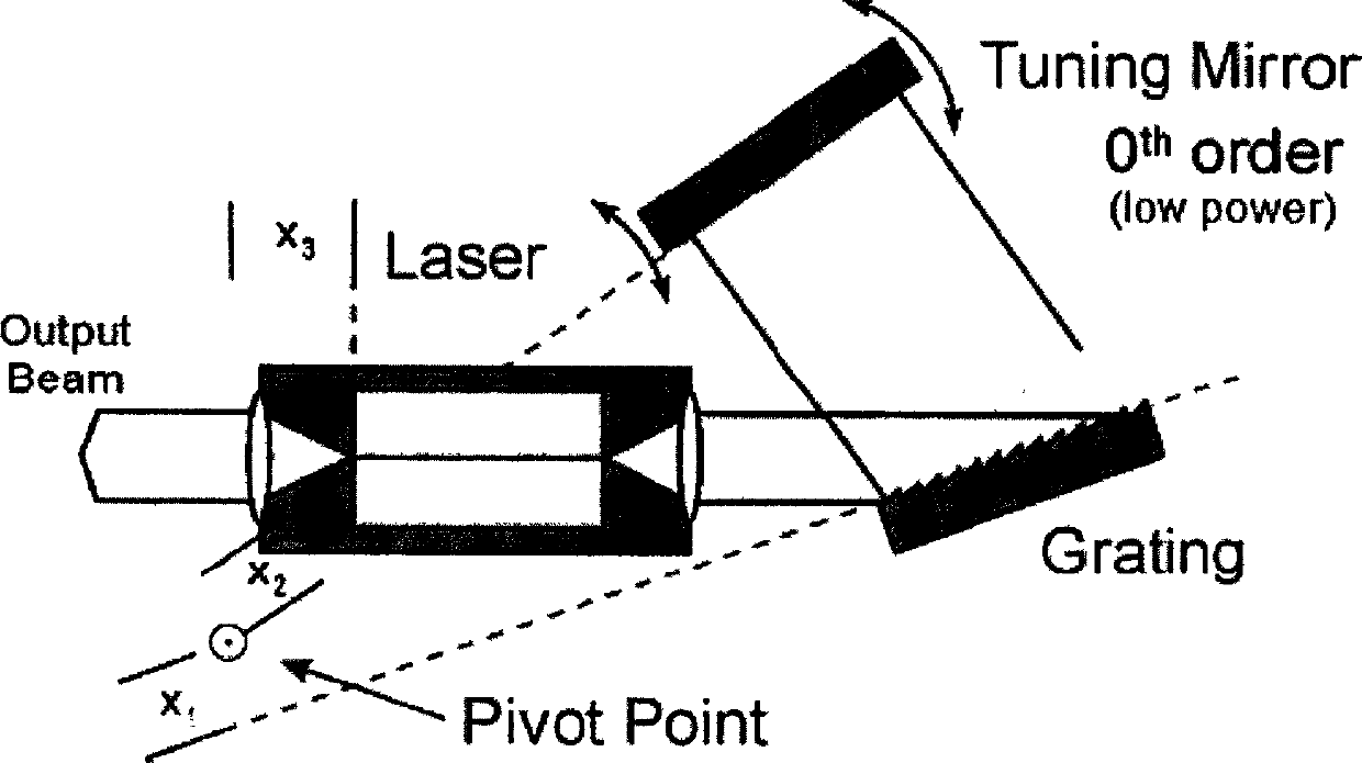
[0045] The technical scheme of the present invention is as Figure 6 , Figure 7 shown. The narrow linewidth laser of the present invention mainly comprises: diode chip (DC) 5, collimating lens (COL) 3,7, grating (GT) 17 or photorefractive crystal 701 (hereinafter represented by grating / photorefractive crystal), and monolithic annular F-P cavity (MFC) 8 . Wherein, the grating 17 can adopt, for example, a holographic grating, a ruled grating, and the like.

[0046] The structure of the monolithic annular F-P cavity in one embodiment of the invention, such as Figure 4As shown, it is a hexahedral structure with an isosceles trapezoidal cross section. Point A on the light input surface enters the ring-shaped F-P cavity,...


PUM


Abstract

The invention discloses a narrow-linewidth laser comprising a DC (Diode Chip), a single annular F-P (Fabry-Perot) cavity and a raster / photorefractive crystal. The arrangement of all parts in the laser enables a laser beam emitted from the rear end of the DC to be output as output light, a laser beam emitted from the front end of the DC enters into the single annular F-P cavity from the input surface of the F-P cavity, is reflected by at least two reflecting surfaces and returned to the incidence point of the input surface, and the beam transmitted through one reflecting surface of the single annular F-P cavity enters the raster / photorefractive crystal and is fed back to the DC in an original path for mold selection. The invention can realize the narrow-linewidth large-power output of the laser, adjust the output frequency in a large single mold range and has good stability, external interference resistance, small size, simple system and convenient use.

Description

technical field [0001] The invention relates to the technical field of semiconductor lasers, in particular to a novel high-power narrow-linewidth laser. Background technique [0002] F-P cavities are important tools in optics and laser research. The transmitted light of the annular F-P cavity has the same spectral structure as the F-P cavity, which can provide narrow linewidth optical feedback. [0003] Currently the annular F-P cavity is constructed of discrete components. For example the structure proposed by Yabai He and Brian J. Orr, see figure 1 As shown, the three mirrors of the ring filter (Ring filter) constitute an equivalent F-P cavity, and the laser beam emitted by the semiconductor laser tube (LD, Laser diode) passes through optical devices such as a collimator lens, a beam splitter, and a partial mirror M1 After being incident into the F-P cavity formed by the Ring filter and oscillating, the transmitted light passes through the partial mirror M2 and finally ...

Claims


Application Information

Patent Timeline
Patent Type & Authority Applications(China)
IPC IPC(8): H01S5/00H01S5/065H01S5/14H01S5/10H01S5/06
Inventor 臧二军彭瑜曹建平李烨方占军
Owner NAT INST OF METROLOGY CHINA
Why Eureka
Try Eureka