Method for wireless data transmission between a measurement module and a transmission unit

A technology of measurement module and transmission unit, which is applied in the direction of measurement devices, wireless architecture, and measurement of electric power, etc., can solve problems such as interference, and achieve the effects of quality improvement, simple method flow, and SNR improvement

Inactive Publication Date: 2014-06-11
AIT AUSTRIAN INST OF TECH
View PDF4 Cites 0 Cited by
  • Summary
  • Abstract
  • Description
  • Claims
  • Application Information

AI Technical Summary

Problems solved by technology

For this reason, disturbances may result during the reception of measurement data, which arise due to the transmission of previously measured measurement data or through simultaneous energy transmission

Method used


Image

  • Method for wireless data transmission between a measurement module and a transmission unit
  • Method for wireless data transmission between a measurement module and a transmission unit
  • Method for wireless data transmission between a measurement module and a transmission unit

Examples


Embodiment Construction

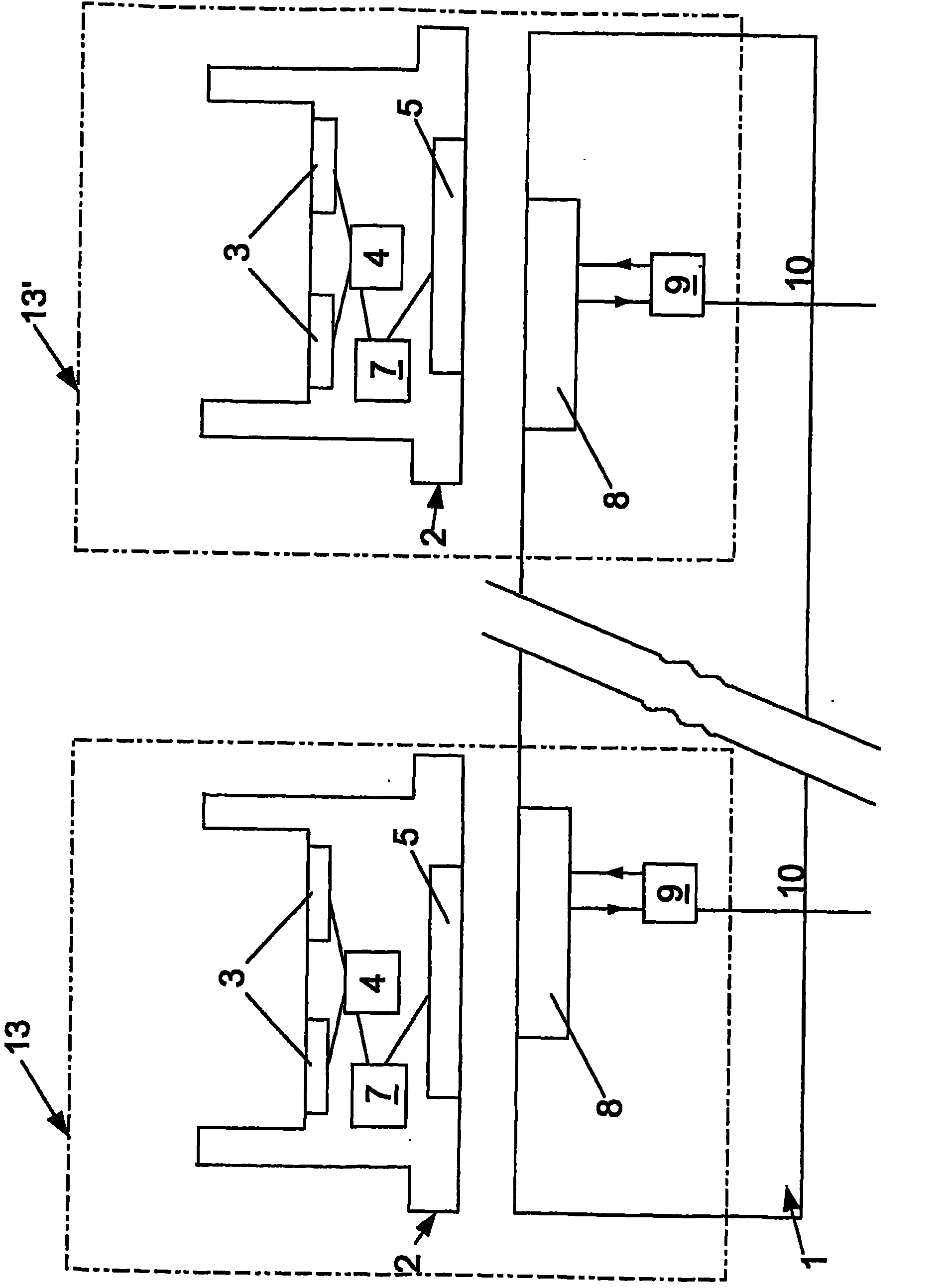
[0015] figure 1 A transmission unit 1 and two measuring modules 2 with which a radio connection is established with this transmission unit 1 are shown. In this case, the transmission unit 1 comprises a plurality of first antennas 8 , wherein each measuring module 2 is assigned a first antenna 8 , wherein the first antennas 8 are located in the vicinity of the measuring module 2 . Assigned to each first antenna 8 is an antenna driver 9 which enables two-way communication with this antenna 8 . Furthermore, a further output of a supply line 10 or a common data line 10 for the plurality of first antennas 8 located in the transmission unit 1 and the respective associated antenna drivers 9 is provided on the antenna driver 9 .

[0016] Above the first antenna 8 a measuring module 2 is shown, which includes a second antenna 5 which is in an electromagnetically active connection with the associated first antenna 8 . Each of the first antennas 8 is arranged directly below the assigne...


PUM


Abstract

A method records and transmits data between a transmission unit that has a first antenna and a measurement module which has a sensor for recording measured variables and converts the measured variables into electric signals. Data is bi-directionally transmitted between the measurement module and the transmission unit located within the near field of the measurement module by use of a second antenna that is arranged on the measurement module. The electromagnetic energy of the signal that is applied to the second antenna is transformed and temporarily stored by a reception unit which is arranged downstream of the second antenna. The first antenna of the transmission unit is put in an inactive state at least during the time the measured variables are sensed by the measurement module or the sensors.

Description

technical field [0001] The invention relates to a method according to the preamble of claim 1 and a device according to the preamble of claim 4 . [0002] The method and the device according to the invention are used in particular for the on-line monitoring and determination of measured variables or biological reactions, in particular electrical properties of cell cultures. Background technique [0003] Usually, in order to determine the biological properties of a sample, the impedance of the sample is determined at one or more predetermined frequencies. From the impedance measured at many different frequencies, the biological properties of the sample can be inferred. For a simple and cost-effective configuration of the measurement, it can be provided that the measurement module, in which the biological sample is located, and the transmission unit, which forwards the measurement data to the central data processing unit, are implemented as separate units. For a simple trans...

Claims


Application Information

Patent Timeline
Patent Type & Authority Patents(China)
IPC IPC(8): H04Q9/00
CPCH04Q2209/84A61B5/0002A61B5/053G01R21/1331H04Q2209/883H04Q9/00H04Q2209/47
Inventor R·希尔H·布雷克尔H·克劳亚思J·维森瓦瑟
Owner AIT AUSTRIAN INST OF TECH
Why Eureka
Try Eureka