
Gear grinding tool and method of using gear grinding tool

A technology for grinding tools and gears, applied in the direction of gear tooth manufacturing tools, gear tooth manufacturing devices, manufacturing tools, etc., can solve the problem that gear grinding tools cannot achieve machining accuracy, the service life of the finishing area is over, and the service life is not available. And other issues

Inactive Publication Date: 2011-04-27
HONDA MOTOR CO LTD
View PDF7 Cites 24 Cited by
  • Summary
  • Abstract
  • Description
  • Claims
  • Application Information

AI Technical Summary

Problems solved by technology

However, a disadvantage of the disclosed gear grinding tool is that the service life of the finishing zone will end earlier than the service life of the rough grinding zone
Thus, the gear grinding tool will likely not be able to achieve the desired level of machining accuracy because the finishing region has a finer grinding surface than the rough-grinding region and tends to wear faster than the rough-grinding region to become unusable
Furthermore, once the finishing area is worn, the rough grinding area that is still usable becomes useless, resulting in an overall shortened service life of the gear grinding tool

Method used


Image

  • Gear grinding tool and method of using gear grinding tool
  • Gear grinding tool and method of using gear grinding tool
  • Gear grinding tool and method of using gear grinding tool

Examples


Embodiment Construction

[0026] Referring to the accompanying drawings, a gear grinding tool according to a preferred embodiment of the present invention is described in detail below regarding a method of using the gear grinding tool.

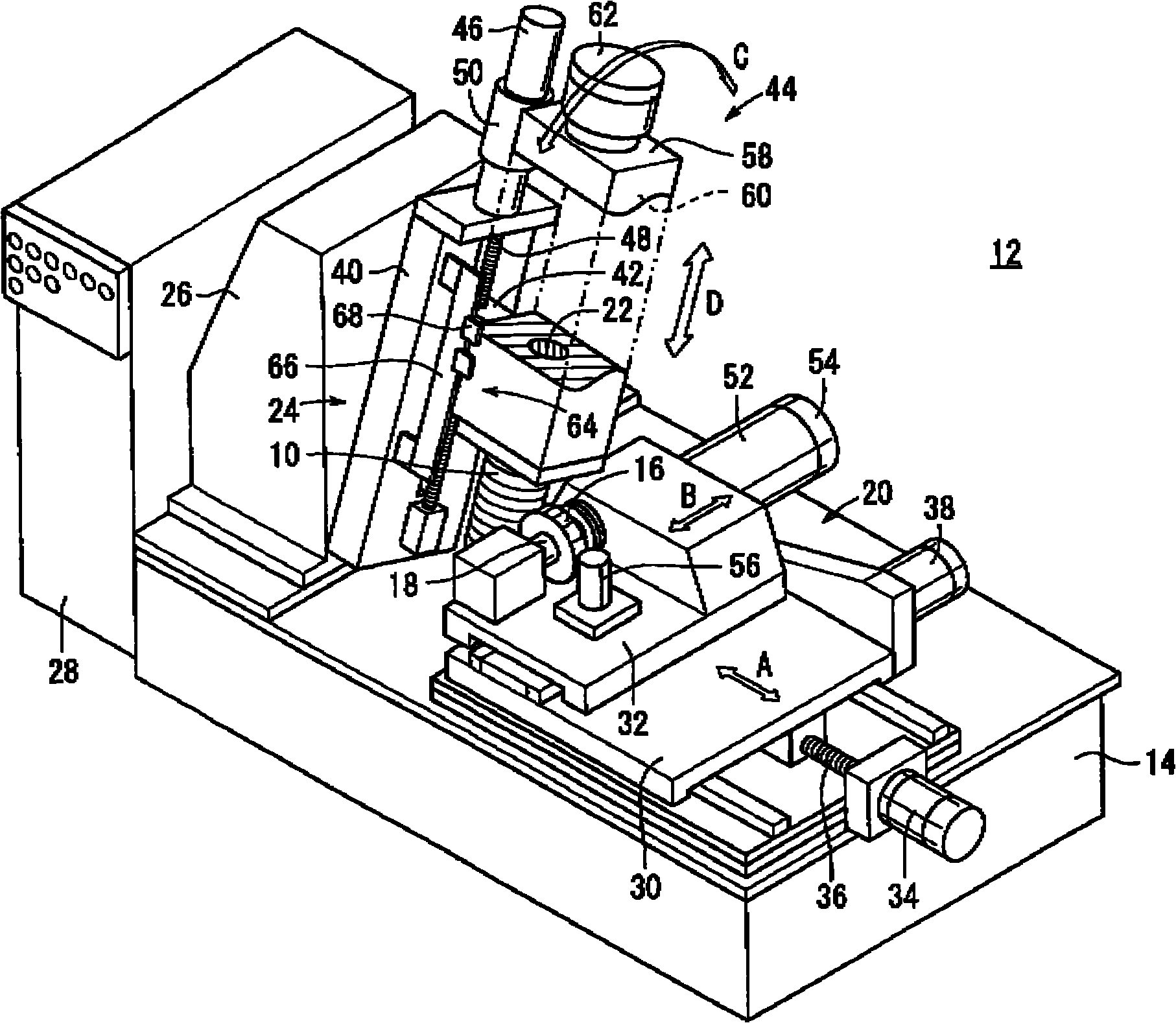
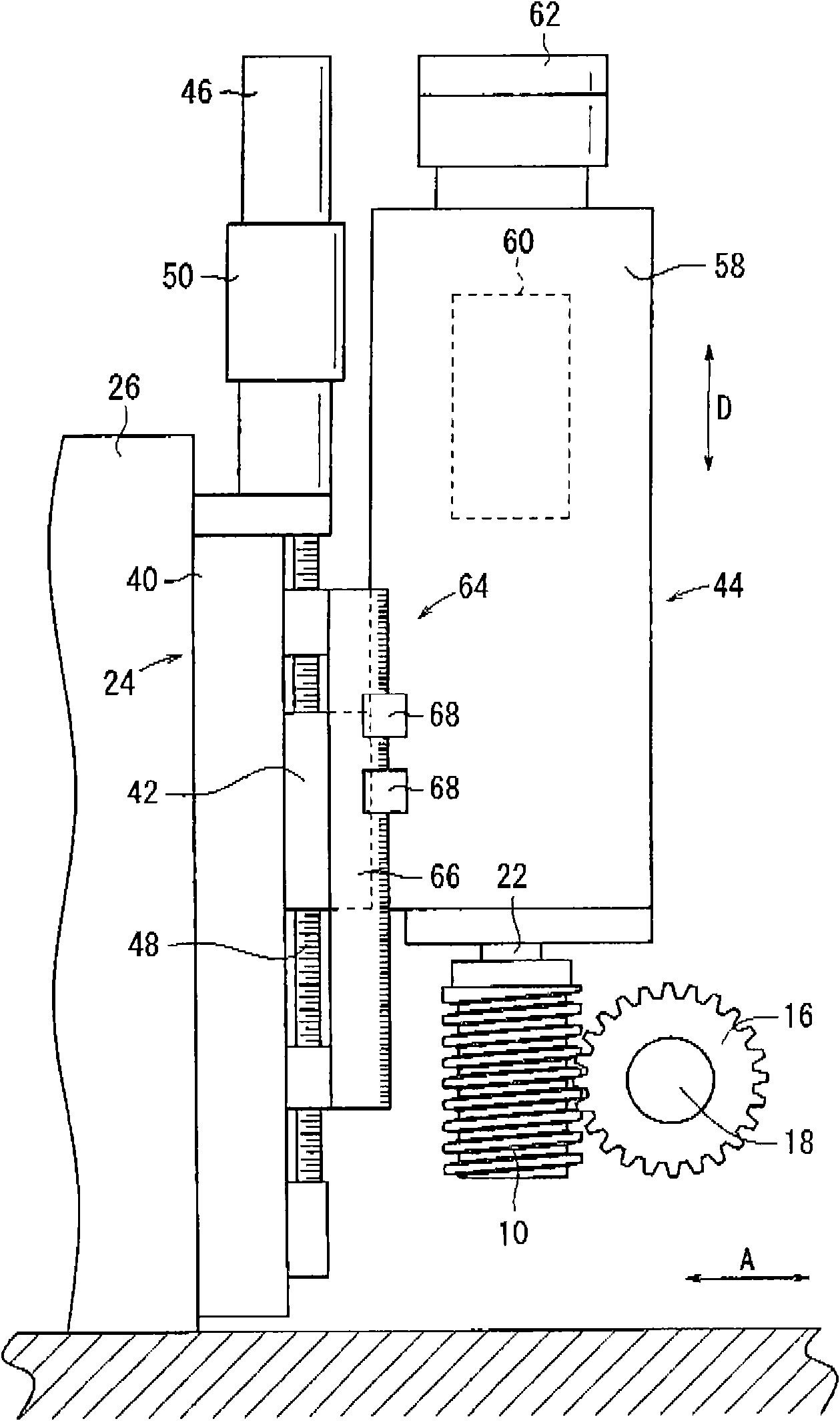
[0027] figure 1 is a perspective view of a gear grinding machine 12 incorporating therein a gear grinding tool 10 according to an embodiment of the present invention. figure 2 yes figure 1 A partial front view of the tool shaft and proximal portion of the gear grinder 12 is shown. The gear grinding tool 10 constitutes a tool mounted on a tool shaft of a gear grinding machine 12 to grind tooth surfaces of gears mounted on a work shaft of the gear grinding machine 12 .

[0028] Such as figure 1 with figure 2 As shown, the gear grinding machine 12 includes: a bed 14; a workpiece shaft 18 for holding a gear 16 to be ground as a workpiece above the bed 14; a movable table mechanism 20 for supporting the workpiece shaft 18 thereon , the workpiece shaft 18 is movable o...


PUM


Abstract

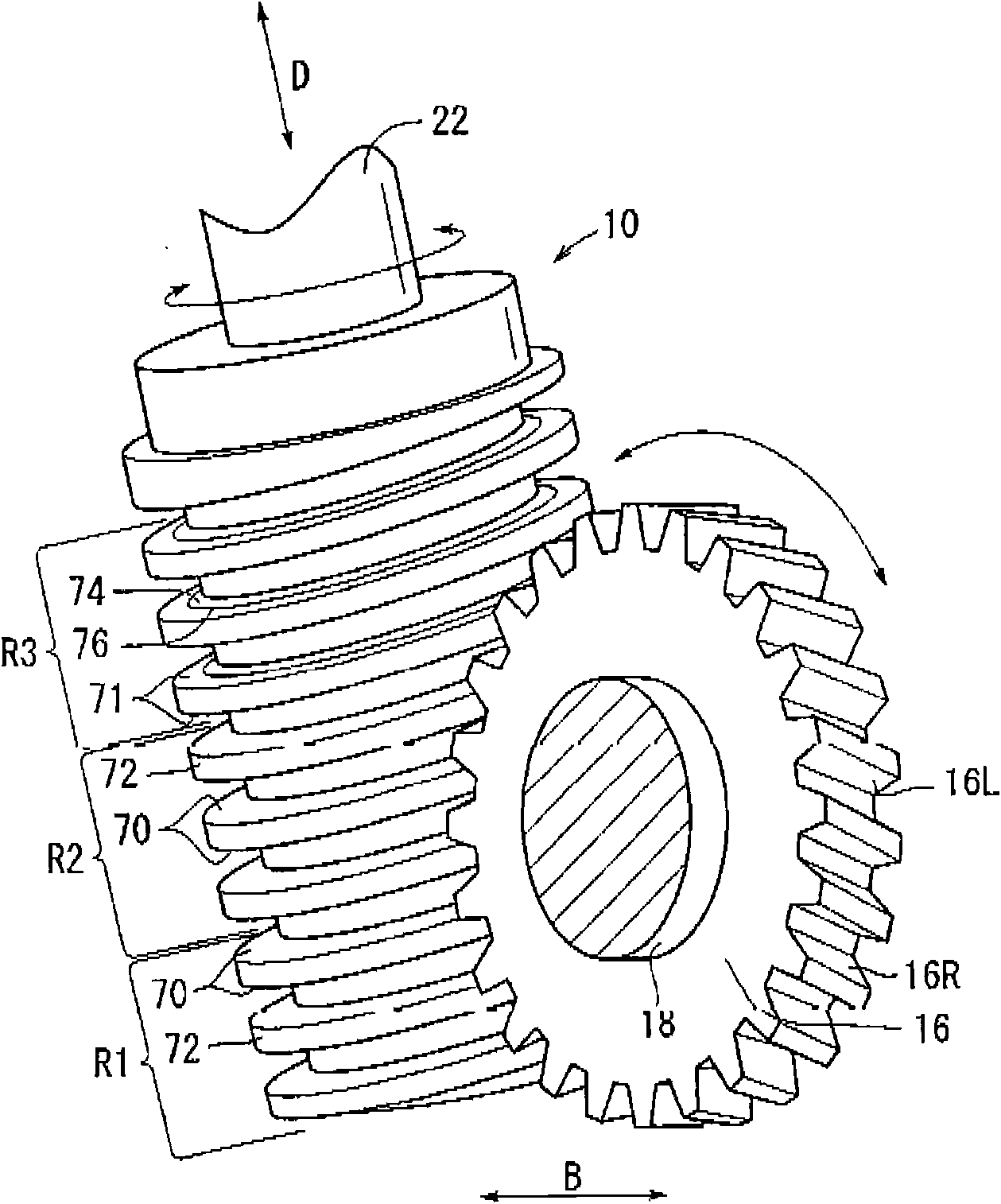
The invention provides a gear grinding tool and a method of using the gear grinding tool.The gear grinding tool (10) comprises a helical tooth (72) with grinding faces (70, 71) on the surfaces thereof.According to the gear grinding tool (10), tooth flanks of gears (16) as workpieces are ground by the grinding faces (70, 71).The grinding face (70) comprises a rough grinding face (74) for performing a rough grinding process.The grinding face (71) comprises a rough grinding face (74) for performing a rough grinding process.The rough grinding face (74) comprises a forming line (76) for performinga fine finishining process.

Description

technical field [0001] The present invention relates to a gear grinding tool having helical teeth that engage a rotating gear to grind the gear. The invention also relates to a method of using such a gear grinding tool. Background technique [0002] Generally, a gear grinding machine includes a tool shaft, which holds a gear grinding tool having helical teeth, and a work shaft, which holds a gear used as a workpiece. During operation, the tool shaft and the workpiece shaft rotate synchronously with each other in order to grind the tooth flanks by the gear grinding tool. [0003] Such tooth flanks are usually ground separately in two stages, a rough grinding stage and a finishing stage. The rough grinding stage and the finishing stage respectively use rough grinding tools and finishing tools to continuously perform corresponding grinding processes on the tooth flanks in order to grind the tooth flanks to the desired finishing degree. [0004] Japanese Patent Laid-Open Publ...

Claims


Application Information

Patent Timeline
Patent Type & Authority Applications(China)
IPC IPC(8): B23F21/02B23F5/04
CPCB23F5/02B23F21/02B23F21/005
Inventor 伊藤达也岩佐直树小川浩高桥启介冨沢佑一松尾泰贵泉田昌宏
Owner HONDA MOTOR CO LTD
Learn More