Axial adjusting device of butterfly valve shaft

A technology for regulating devices and butterfly valves, which is applied in the direction of valve devices, lifting valves, engine components, etc., can solve the mismatch between the sealing ring of the valve body and the sealing ring of the butterfly plate, and the inaccuracy of the cooperation between the sealing ring of the valve body and the sealing ring of the butterfly plate Advanced problems, to achieve the effect of high precision

Inactive Publication Date: 2011-04-27
LIAONING NENGFA WEIYE ENERGY TECH CO LTD
View PDF6 Cites 3 Cited by
  • Summary
  • Abstract
  • Description
  • Claims
  • Application Information

AI Technical Summary

Problems solved by technology

When assembling the butterfly valve, the valve shaft must be adjusted axially so that the sealing ring of the valve body and the sealing ring of the butterfly plate are closely matched. In the prior art, the valve shaft is adjusted axially by adjusting the gap between the lower end of the valve shaft and the end cover. Adjusting the gap between the lower end of the valve shaft and the end cover is to adjust the thickness of the circular friction pad or add a circular pad under the circular friction pad; when the butterfly valve is used vertically, the friction pad will be affected by the rotation of the valve shaft. The wear causes the thickness of the friction pad to decrease, and the reduction of the thickness of the friction pad will cause the valve shaft to move downward in the axial direction, causing the valve body sealing ring and the butterfly plate sealing ring to lose fit. In order to restore the valve body sealing ring and the butterfly plate For the matching accuracy of the sealing ring, the valve shaft should be adjusted upwards in the axial direction, so that the sealing ring of the valve body and the butterfly plate sealing ring can restore the matching accuracy. The method of axially adjusting the valve shaft by the gap between the covers, the above method of axially adjusting the valve shaft is not only troublesome, because the method of adding a ring gasket makes the axial displacement of the valve shaft discontinuous in stages, so the axial adjustment After the valve shaft, the matching accuracy of the sealing ring of the valve body and the sealing ring of the butterfly plate is not high

Method used


Image

  • Axial adjusting device of butterfly valve shaft
  • Axial adjusting device of butterfly valve shaft
  • Axial adjusting device of butterfly valve shaft

Examples


Embodiment Construction

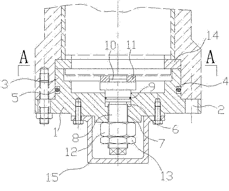
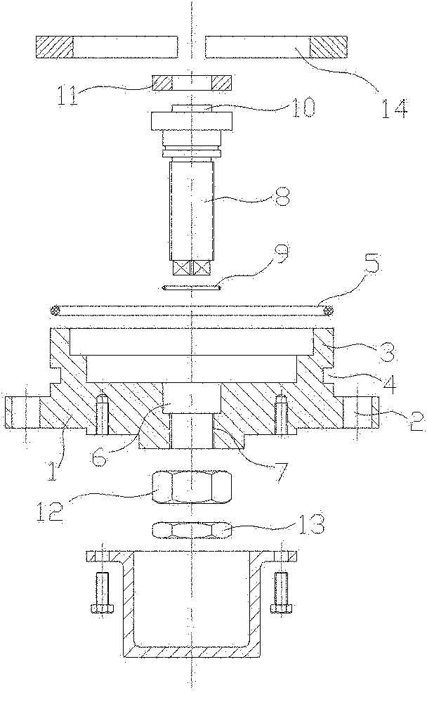
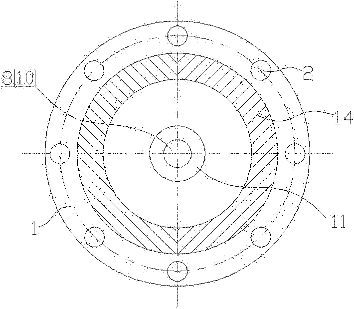
[0014] Figure 1~Figure 3 Among them, the axial adjustment device of the butterfly valve shaft has a circular end cover 1, the outer circumference of the end cover surface is evenly distributed with axial circular holes 2, and the top of the end cover is connected with a raised cylinder 3, and the end cover cylinder There is a groove 4 along the circumference on the outer circumference, a sealing ring 5 is arranged in the groove, a round hole 6 is arranged in the center of the end cover, and the lower section of the round hole is an internally threaded hole 7, and an adjusting screw 8 is screwed inside the internally threaded hole section. There is a sealing ring 9 between the adjusting screw and the upper section of the round hole, the upper end of the adjusting screw has a circular protrusion 10, the circular protrusion is covered with a circular friction pad 11, and the lower end of the adjusting screw is screwed with a fastening nut 12 in turn. With fastening nut 13, the u...


PUM


Abstract

The invention discloses an axial adjusting device of a butterfly valve shaft. Axial round holes are uniformly distributed in the outer circumference of a round end cover; the upper part of the end cover is connected with a convex cylinder; a sealing groove is arranged on the cylinder of the end cover; an adjusting screw is screwed in the center of the end cover; a sealing ring is arranged between the adjusting screw and the round hole; a round protrusion is arranged at the upper end of the adjusting screw; an annular friction pad is sleeved on the round protrusion; a fastening nut and a binding nut are sequentially screwed at the lower end of the adjusting screw; a split ring comprising two half rings is supported against and connected with the upper end of the cylinder of the end cover; and a protective cover connected by screws is arranged at the end face of the end cover. In the invention, the rotatable adjusting screw is arranged on the end cover; the friction pad is arranged at the upper end of the adjusting screw; after the butterfly valve is assembled, the friction pad is closely supported against the lower end face of the valve shaft; the valve shaft can continuously move along the axial direction conveniently by rotating the adjusting screw; and when the butterfly valve is assembled, debugged and overhauled, the fit between the sealing ring of the valve body and a sealing ring of a butterfly plate can be conveniently adjusted, so that the fit precision between the sealing ring of the valve body and the sealing ring of the butterfly plate is higher.

Description

technical field [0001] The invention relates to a part of a butterfly valve, in particular to an axial adjustment device for a valve shaft of a butterfly valve. Background technique [0002] The butterfly valve has a cylindrical valve body. There are upper and lower valve shaft seats opposite to each other on the upper and lower sides of the valve body circumference. There is a valve shaft perpendicular to the axis of the valve body cylinder between the upper and lower valve shaft seats. There is a drive device for the valve shaft on the upper valve shaft seat of the valve body, and a circular end cover is connected under the lower valve shaft seat of the valve body. The outer circumference of the end cover surface is evenly distributed with axial round holes. There is a circular protrusion in the middle, and there is a circular friction pad on the circular protrusion of the end cover, between the lower end of the valve shaft and the end cover, and the section of the valve s...

Claims


Application Information

Patent Timeline
Patent Type & Authority Applications(China)
IPC IPC(8): F16K1/32F16K1/22
Inventor 李振春
Owner LIAONING NENGFA WEIYE ENERGY TECH CO LTD
Why Eureka
Try Eureka