Conjugated dendritic electrically-induced pure red material and preparation method and use thereof

A dendritic and conjugated technology, applied in luminescent materials, chemical instruments and methods, circuits, etc., can solve the problems of reduced luminous efficiency of devices, aggregation of small molecule luminescent materials, unsuitable for industrialized large-scale production, etc., to reduce excitation Formation of base complexes, reduction of fluorescence self-quenching, and improvement of energy transfer efficiency

Inactive Publication Date: 2011-06-15
PEKING UNIV
View PDF0 Cites 0 Cited by
  • Summary
  • Abstract
  • Description
  • Claims
  • Application Information

AI Technical Summary

Problems solved by technology

However, this type of method has high requirements for the doping process. The range of small molecule materials doped in the parent material is very narrow. If the concentration is too high, the small molecule light-emitting materials will aggregate and self-quenching will occur. If the concentration is too low, the device will be damaged. The overall luminous efficiency is reduced, and at the same time, part of the energy of the matrix material is self-luminous because it cannot be completely transferred, which reduces the color purity of the device
At the same time, the doping process makes the fabrication of the device complicated and is not suitable for industrialized mass production.
At the end of the last century, people began to try to use conjugated dendrimers to prepare red light materials, and synthesized a class of derivatives with porphyrin as the core and conjugated or non-conjugated dendrimers as the arms, but due to the synthesis of such materials Due to the difficulty on the surface and the structure of the molecule itself, the energy transfer between molecules and molecules is not sufficient, so there is no report on the efficiency of typical OLED devices.

Method used


Image

  • Conjugated dendritic electrically-induced pure red material and preparation method and use thereof
  • Conjugated dendritic electrically-induced pure red material and preparation method and use thereof
  • Conjugated dendritic electrically-induced pure red material and preparation method and use thereof

Examples


Embodiment 1

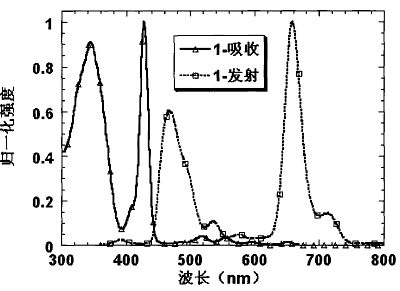
[0031] Embodiment 1: Preparation of compound 1 and its property determination

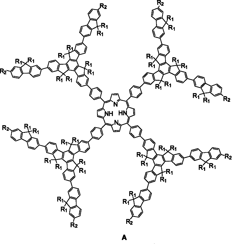
[0032] Suzuki reaction of bromide 3 with boronate 4 as shown below affords compound 5. Compound 1 is then obtained under the catalysis of boron trifluoride:

[0033]

[0034] where: R 1 =n-C 6 h 13

[0035] (1) Preparation of Compound 5:

[0036] Bromide 3 (0.15mmol), borate 4 (0.90mmol), potassium phosphate (1.80mmol) and catalyst Pd(PPh 3 ) 4 (5mol%) is added in the three-necked reaction flask that reflux condenser is installed, degasses with oil pump, blows into N 2 , repeat 3 times. Inject the bubbling degassed toluene and deionized water with a needle, degas again with an oil pump, and blow in N 2 , repeat 3 times. The mixed solution was refluxed for 24 hours under heating in an oil bath. After cooling to room temperature, the reaction was quenched by adding saturated ammonium chloride solution, extracted with ethyl acetate (3×100 mL), the organic phase was washed with saturated ...

Embodiment 2

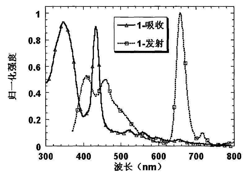
[0048] Embodiment 2: Preparation of compound 2 and its property determination

[0049] When preparing long oligomeric fluorene units, the synthesis method shown in the figure below is used:

[0050]

[0051] (1) Preparation of compound 6:

[0052] Compound 3 (1.0mmol), 1,3-propanediol (2.0mmol), p-toluenesulfonic acid (0.05mmol) were dissolved in toluene (50ml), and the mixed solution was heated and refluxed to TLC to detect that the raw material compound 3 had been consumed (about 4-6 hours), the reaction solution was left to room temperature, washed with deionized water, washed with saturated brine, dried over magnesium sulfate, and spin-dried to obtain a mixture purified by column chromatography (100-200 mesh silica gel, developer: petroleum ether / ethyl acetate=30: 1), product 6 is a white solid, yield: 92%.

[0053] 1 H NMR (CDCl 3 , 300Hz, ppm): δ 8.37-8.34 (Ar-H, 1H, d, J=8.4Hz), 8.24-8.17 (Ar-H, 2H, m,), 7.74-7.71 (Ar-H, 2H, d , J=8.4Hz), 7.65-7.50 (Ar-H, 8H, m)...

Embodiment 3

[0076] Embodiment 3: device making

[0077] The typical device manufacturing process of the present invention is as follows: ITO (indium tin oxide) glass is ultrasonicated for ten minutes with acetone, alkaline washing solution, pure water (twice), and isopropanol, and then treated with ozone plasmar for 5 minutes. The hole injection layer PEDOT (poly(3,4-ethylenedioxythiophene)) was spin-coated on the treated substrate to form a film with a thickness of 50 nm, and was heated in air at 160° C. for 6 minutes. A hole transport layer PVK (poly(9-vinylcarbazole)) (thickness 40 nm) was spin-coated thereon, and heated for 15 minutes in a nitrogen atmosphere. Then spin-coat the light-emitting layer (compound 1 or 2, thickness 60 nm), and heat for 15 minutes in a nitrogen atmosphere. Finally, Ba / Al (with a thickness of 4.5nm / 150nm) is vacuum evaporated to complete the device. The device structure is ITO / PEDOT(50nm) / Compound 1 or 2(60nm) / Ba(4.5nm) / Al(150nm) or ITO / PEDOT(50nm) / PVK(40nm)...


PUM

PropertyMeasurementUnit
luminanceaaaaaaaaaa

Abstract

The invention provides conjugated dendritic pure red light emitting electroluminescent material, and a preparation method and application thereof. The material has a conjugated dendritic molecule which takes porphyrin as a core, truxene as a bridge and monofluoride as an antenna molecular and has a structural formula A. The material is prepared by the Lindsey condensation reaction of a derivativehaving a methanoyl of the truxene and the porphyrin. The method introduces a truxene system having a hydrotropic group to a metaposition of a porphyrin molecule to improve the solubility of the material and suppress fluorescence self-quenching, and increases intramolecular and intermolecular energy transfer through derivatization at 2, 7, 12-position of the truxene, so as to obtain high-efficiency pure light emission. The conjugated dendritic molecules are used as materials for a light emitting layer of an organic electroluminescent diode device and made into films by a simple spin coating process, and generate high-efficiency pure red light electrofluorescence without doping.

Description

technical field [0001] The invention relates to the field of organic electroluminescent materials, in particular to a novel stable conjugated dendritic molecular material and a preparation method thereof, which can be used as a pure red light material in a light-emitting layer of an organic electroluminescent diode (OLED). Background technique [0002] In recent years, organic light-emitting diode (OLED) has gradually become an important development direction in the field of flat-panel display. more attention. In OLED devices, holes are injected from the anode and electrons are injected from the cathode under an electric field, and the excitons are recombined in the organic light-emitting layer, and finally the excitons are withdrawn to emit visible light. Generally, good organic light-emitting materials must have high quantum efficiency, good film-forming properties, and excellent optical and electrical stability. OLED light-emitting materials can be divided into two cate...

Claims


Application Information

Patent Timeline
Patent Type & Authority Patents(China)
IPC IPC(8): H01L51/52C07D487/22H01L51/54C09K11/06
Inventor 裴坚段晓菲
Owner PEKING UNIV
Why Eureka
Try Eureka