Automatic grinding device and grinding method

A grinding and automatic technology, applied in the direction of grinding/polishing safety devices, grinding machines, grinding workpiece supports, etc., can solve the problems of difficult control of force, high processing cost, and low removal efficiency, so as to achieve high grinding efficiency and improve The degree of automation and the effect of saving labor costs

Active Publication Date: 2019-03-15
CHANGZHOU INNO MACHINING
View PDF5 Cites 0 Cited by
  • Summary
  • Abstract
  • Description
  • Claims
  • Application Information

AI Technical Summary

Problems solved by technology

[0006] For this reason, the technical problem to be solved by the present invention is that the post-treatment process of solid laser cutting uses a scraper to remove the slag generated by cutting, which is difficult to control, the slag damages the scraper greatly, and the removal efficiency is low, and the processing cost is high. Propose an automatic grinding device and grinding method with high efficiency and low cost

Method used


Image

  • Automatic grinding device and grinding method

Examples


Embodiment 1

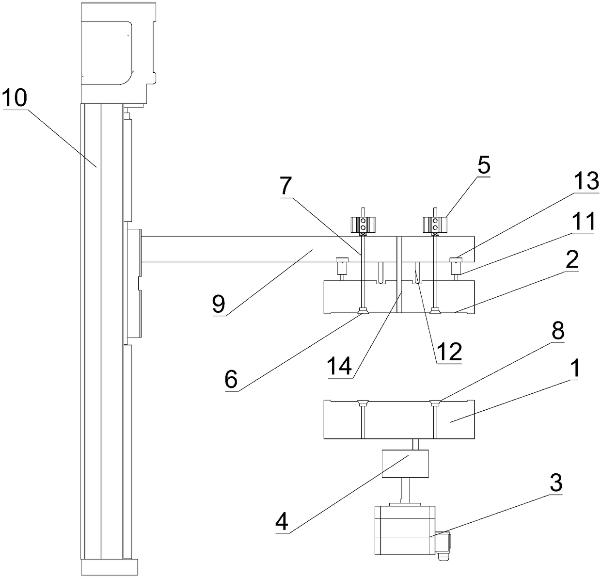
[0031] This embodiment provides an automatic grinding device, such as figure 1 As shown, it includes a first jig 1 and a second jig 2 that are relatively arranged and can perform relative rotational movement. The first jig 1 and the second jig 2 are made of Teflon, and the first jig 1 and the second jig 2 can be buckled into a complete jig, and two workpieces to be ground such as ceramics, sapphire, etc. are respectively fixed in the first jig 1 and the second jig 2, and the two workpieces The slag surface is oppositely arranged (after the workpiece is drilled and cut, a slag protrusion will be formed at the hole entrance).

[0032] Place workpieces such as ceramics between two fixtures, control the relative rotation of the two fixtures to drive the relative rotation of the two workpieces, and use the friction between the two workpieces to remove the slag. It will not cause damage to the workpiece during the process. This device solves the problems of large shovel plate loss ...

Embodiment 2

[0039] The present embodiment provides an automatic grinding method, which includes the following steps:

[0040] S1. Place two workpieces to be ground in the first jig 1 and the second jig 2 respectively, and the slag surfaces of the workpieces are set opposite to each other. Specifically, place a piece of workpiece slag face up on the first jig In 1, the second vacuum nozzle 8 is turned on to make the workpiece be absorbed and fixed, and the telescopic cylinder 5 drives the first vacuum nozzle 6 to grab another piece of workpiece. The slag of the workpiece faces downward and the workpiece is absorbed and fixed by the first vacuum nozzle 6 ;

[0041] S2. The lifting electric cylinder 10 drives the second jig 2 down to the contact between the slag surfaces of the two workpieces according to the feed rate of 0.1 mm. The moving distance is set according to the height of the slag surfaces. The force is controlled by the air spring, and the pressure sensor 13 Return pressure data...

Embodiment 3

[0044] The present embodiment provides an automatic grinding method, which includes the following steps:

[0045] S1. Place two workpieces to be ground in the first jig 1 and the second jig 2 respectively, and the slag surfaces of the workpieces are set opposite to each other. Specifically, place a piece of workpiece slag face up on the first jig In 1, the second vacuum nozzle 8 is turned on to make the workpiece be absorbed and fixed, and the telescopic cylinder 5 drives the first vacuum nozzle 6 to grab another piece of workpiece. The slag of the workpiece faces downward and the workpiece is absorbed and fixed by the first vacuum nozzle 6 ;

[0046] S2. The lifting electric cylinder 10 drives the second jig 2 down to the contact between the slag surfaces of the two workpieces according to the feed rate of 100 mm. The moving distance is set according to the height of the slag surfaces. Pressure data return;

[0047] S3, start the rotating motor 3 and the reduction box 4 to ...


PUM


Abstract

The invention discloses an automatic grinding device and a grinding method. The device comprises a first jig and a second jig which are arranged oppositely and can rotate relatively; workpieces to be ground are fixed on the first jig and the second jig respectively, and molten slag surfaces of the workpieces to be ground are arranged oppositely. The device adopts the two jigs capable of rotating relatively and workpieces including ceramic and the like are arranged between the two jigs; the two jigs are controlled to rotate relatively so that the two workpieces are driven to rotate relatively; molten slag is removed by utilizing friction force between the two workpieces; the rigidity of materials of the workpieces is consistent, so that damages to the materials are not caused in a rubbing process; and the problems that the loss of a shovel plate and the materials are prone to being damaged in a traditional grinding process are solved by the device. By adopting the device and the method, two workpieces can be machined simultaneously, so that the grinding efficiency is high and the cost is low.

Description

technical field [0001] The invention belongs to the technical field of laser cutting, and relates to a laser cutting post-processing device, in particular to an automatic grinding device and a grinding method. Background technique [0002] Laser cutting is a kind of laser beam focused on the surface of the material by using the focusing lens, the formed high power density laser beam makes the material melt or vaporize rapidly, and makes the laser beam and the material move relative to each other along a certain trajectory, thus forming a certain shape of the slit , The thermal processing method to realize workpiece cutting has been widely used in the cutting process of hard and brittle materials, such as machine tools, engineering machinery, electrical switch manufacturing, elevator manufacturing, grain machinery, textile machinery, locomotive manufacturing, agricultural and forestry machinery, food machinery , special vehicles, petroleum machinery manufacturing, aerospace, ...

Claims


Application Information

Patent Timeline
Patent Type & Authority Patents(China)
IPC IPC(8): B24B9/06B24B41/06B24B41/00B24B55/02
CPCB24B9/06B24B41/00B24B41/06B24B55/02
Inventor 韩世华周蕊沈丹鸿
Owner CHANGZHOU INNO MACHINING
Why Eureka
Try Eureka