Gas discharge tube with shielded ceramic sheet

A technology of gas discharge tubes and ceramic tubes, applied in the direction of cold cathode tubes, solid cathode components, etc., can solve the problems of high current density, the width and length of the conductive strip are not an effective solution, large current, etc., and achieve the goal of reducing the protection level Effect

Active Publication Date: 2017-12-08
EPCOS ELECTRONICS XIAOGAN
View PDF4 Cites 0 Cited by
  • Summary
  • Abstract
  • Description
  • Claims
  • Application Information

AI Technical Summary

Problems solved by technology

[0002] Existing gas discharge tubes for power supply protection, after the lightning shock of In and Imax in its specifications, its protection level will increase sharply by 50% to 100% compared with that before the lightning shock, which can no longer meet the low protection requirements in the current market. The level is getting higher and higher. Since the conductive strip on the inner wall of the ceramic tube directly reduces the protection level of the gas discharge tube, the gas discharge tube in the industry always seeks a breakthrough in the improvement of the conductive strip on the inner wall of the ceramic tube when it comes to reducing the protection level. But the effect is not obvious
[0003] When the current power protection gas discharge tube is struck by lightning, due to the large current (up to tens of thousands of amps or hundreds of thousands of amps), the power-on time is extremely short (8 / 20us), so the current density is huge and the electrons move fast. Under the impact of high-speed and high-density electrons, the temperature of electronic powder and metal surface will also rise sharply, so the particles of electronic powder and metal surface will splash to the inner wall of the ceramic under the double action of high-speed, high-density electron impact and high-temperature evaporation, resulting in The wall conductive strip is completely shielded by the splash, the effect of the conductive strip is reduced, and the protection level will increase sharply
Therefore, only improving the width and length of the conductive strip is not an effective solution,

Method used


Image

  • Gas discharge tube with shielded ceramic sheet
  • Gas discharge tube with shielded ceramic sheet

Examples


Embodiment Construction

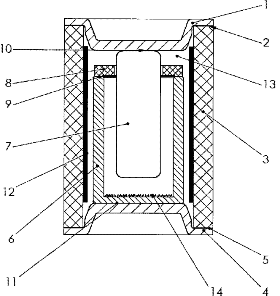
[0010] The present invention adopts the following structure: a gas discharge tube with a shielding ceramic sheet, including a ceramic tube 3, a side electrode 1 at the upper end of the ceramic tube 3, and a lower electrode 4 at the lower end, and a conductive strip 12 is arranged on the inner wall of the ceramic tube 3, The inner cavity of the ceramic tube 3 is filled with an inert gas 13, the electronic powder 14 is placed at the bottom of the tube electrode 6, the column electrode 7 is placed in the tube electrode 6, and a shielding ceramic sheet 8 is welded on the open end of the tube electrode 6.

[0011] In the present invention, the side electrode 1 and the column electrode 7 are welded together at 900±30° C. through the silver-copper solder 10; It is sealed into one body at 30°C; the conductive strip 12 is made of 4H lead core, and the inner wall of the ceramic tube 3 is drawn; the ceramic tube 3 is welded with the side electrode 1 and the bottom electrode 4 by silver-co...


PUM


Abstract

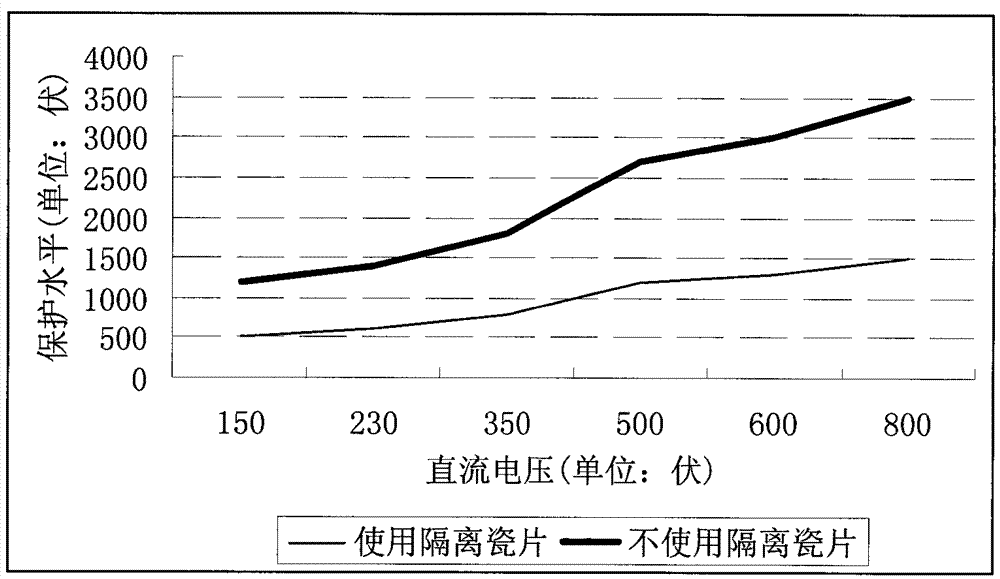
A gas discharge tube with a shielding ceramic sheet, comprising a ceramic tube, a side electrode at the upper end of the ceramic tube, and a lower electrode at the lower end of the ceramic tube, a conductive strip is arranged on the inner wall of the ceramic tube, the inner cavity of the ceramic tube is filled with inert gas, and the electronic powder is placed in the tube At the bottom of the electrode, the column electrode is placed in the tube electrode, and a shielding ceramic sheet is welded at the open end of the tube electrode. In the present invention, a shielding ceramic sheet is welded at the open end of the tube electrode. When the gas discharge tube passes a large current, the shielding ceramic sheet well blocks the splash, protects the conductive band, and effectively reduces the protection level. After using the isolation ceramic sheet, The protection level of the gas discharge tube only increases by 10% to 30% after the impact of high current, while the protection level of the same type of gas discharge tube without isolation ceramics rises by 50% to 100%.

Description

technical field [0001] The invention relates to a gas discharge tube used in lightning strike protection for live wires and neutral wires in a power supply system. Background technique [0002] Existing gas discharge tubes for power supply protection, after the lightning shock of In and Imax in its specifications, its protection level will increase sharply by 50% to 100% compared with that before the lightning shock, which can no longer meet the low protection requirements in the current market. The level is getting higher and higher. Since the conductive strip on the inner wall of the ceramic tube directly reduces the protection level of the gas discharge tube, the gas discharge tube in the industry always seeks a breakthrough in the improvement of the conductive strip on the inner wall of the ceramic tube when it comes to reducing the protection level. But the effect is not obvious. [0003] When the current power protection gas discharge tube is struck by lightning, due ...

Claims


Application Information

Patent Timeline
Patent Type & Authority Patents(China)
IPC IPC(8): H01J17/16H01J17/40
Inventor 刘兵洪家平张玉何才云姚景波
Owner EPCOS ELECTRONICS XIAOGAN
Why Eureka
Try Eureka