Electro-acoustic transducer

A technology of electro-acoustic transducers and magnetic components, applied in the direction of sensors, electrical components, etc., can solve the problems of reducing the quality of the speaker 1, the variation of the acoustic performance of the speaker 1, and the increase of the overall height of the speaker 1, so as to avoid the impact of the acoustic performance, The effect of omitting the sticking process and improving the acoustic performance

Inactive Publication Date: 2013-11-06
MERRY ELECTRONICS CO LTD
View PDF4 Cites 1 Cited by
  • Summary
  • Abstract
  • Description
  • Claims
  • Application Information

AI Technical Summary

Problems solved by technology

[0007] However, in the assembly process of the speaker 1, it is necessary to paste the tuning net 17 to obtain better acoustic performance, so that the assembly cost cannot be effectively reduced, resulting in the restriction of industrial competition. At the same time, the tuning net 17 is used as the speaker. 1, in addition to the height of the tuning net 17 itself, if excessive glue is used, it will easily lead to an increase in the overall height of the speaker 1, which is not conducive to the miniaturization design of the speaker. Furthermore, the tuning net 17 will be pasted When it is on the vent hole 10b of the housing 10, there is a possibility that the glue will overflow and block some of the mesh holes, which will greatly affect the sound output of the speaker 1.
[0008] In addition, when the lower piece 16 is injection molded in the housing 10, the lower piece 16 is buried in the installation hole 10a of the housing 10, so that the lower piece 16 and the housing 10 are integrally formed. However, the edge wall thickness of the lower piece 16 is too thin, so that the lower piece 16 The bonding effect between the sheet 16 and the housing 10 is not stable, and when the bottom of the speaker 1 is under pressure, it is easy to cause looseness between the internal structures, so that the acoustic performance of the speaker 1 is changed, and the quality of the speaker 1 is reduced. Therefore, the above-mentioned conventional Speaker 1 still has shortcomings, there is room for improvement

Method used


Image

  • Electro-acoustic transducer
  • Electro-acoustic transducer
  • Electro-acoustic transducer

Examples


Embodiment Construction

[0079] In order to further explain the technical means and effects of the present invention to achieve the intended purpose of the invention, the specific implementation, structure, steps, characteristics and features of the electroacoustic transducer proposed according to the present invention will be described below in conjunction with the accompanying drawings and preferred embodiments. Its effect is described in detail below.

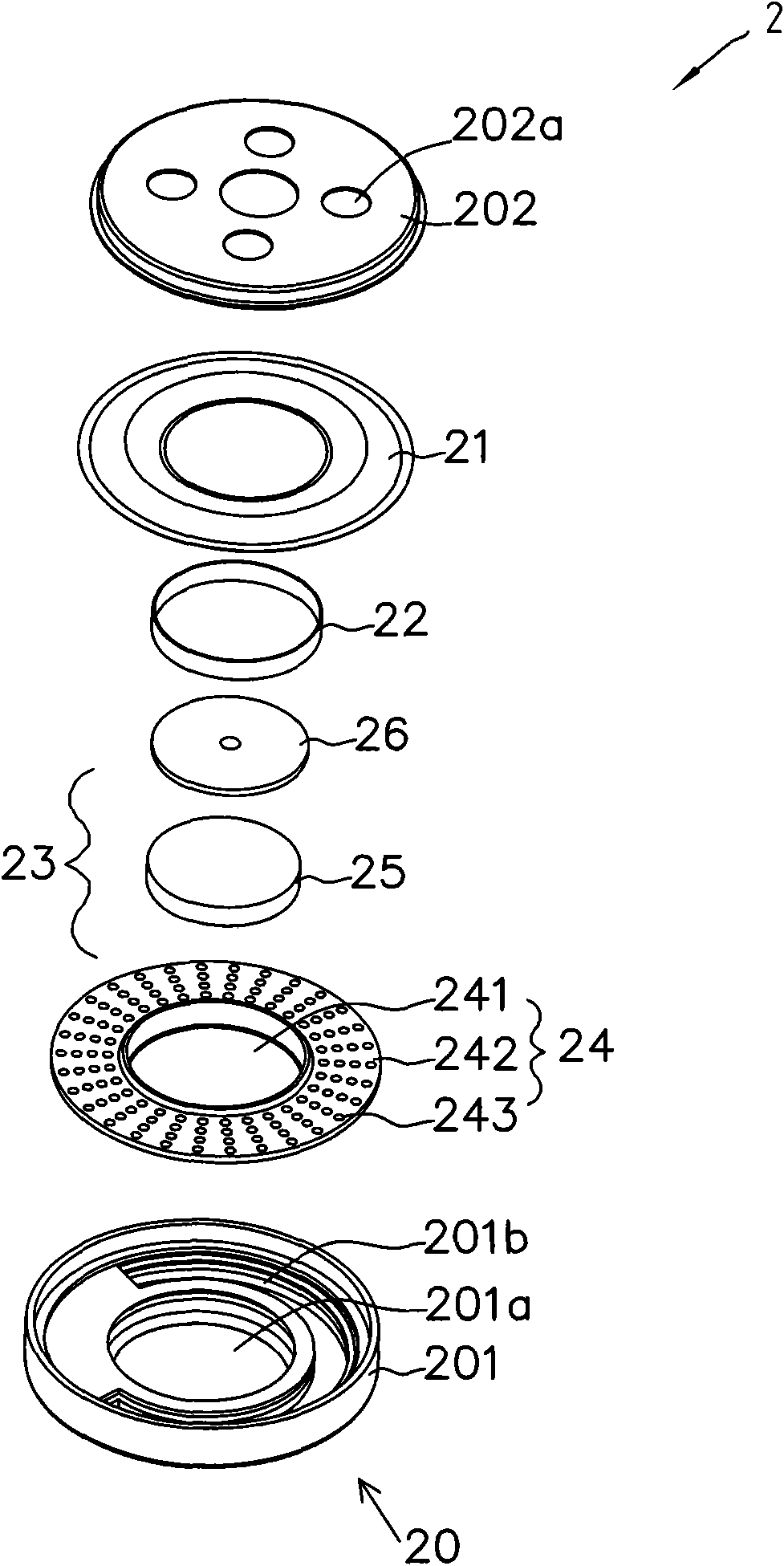
[0080] see image 3 , which is an exploded perspective view of the first embodiment of the electroacoustic transducer of the present invention. Such as image 3 As shown, the electroacoustic transducer 2 includes a casing 20 , a vibrating membrane 21 , a voice coil 22 and a magnetic driving device 23 .

[0081] The above-mentioned casing 20 is made of plastic, and is composed of a base 201 and a cover 202. The base 201 has a mounting hole 201a in the center, and a ventilation hole 201b is formed on the edge of the mounting hole 201a. The upper co...


PUM


Abstract

The invention relates to an electro-acoustic transducer. The electro-acoustic transducer comprises a shell, a voice coil, a vibration diaphragm and a magnetic driving device, wherein one end of the shell is provided with a ventilation hole and the other end of the shell is provided with a voice outlet hole; the voice coil is arranged in the shell; the vibration diaphragm is combined with the top end of the voice coil and can be interlinked along with the voice coil; the magnetic driving device is used for driving the voice coil to vibrate and provided with a combining region and a damping region; and the combining region is buried in a part of the shell, and the damping region is formed on a path from the vibration diaphragm to the ventilation hole so as to adjust voice outlet air volume of the ventilation hole.

Description

technical field [0001] The present invention relates to an electro-acoustic converter, in particular to an electro-acoustic converter which uses the existing components of the electro-acoustic converter to be embedded in a housing and serves as a tuning structure. Background technique [0002] With the ever-changing market demand, various electronic products are developing more rapidly. Among them, the speaker is an important component of the sound output end of the electronic product. The requirements for the speaker are also designed in the direction of miniaturization, high sound quality, and low cost. Meet the needs of the market. [0003] see figure 1 , which is an exploded perspective view of an existing loudspeaker. Such as figure 1 As shown, the speaker 1 includes a casing 10 , an upper cover 11 , a diaphragm 12 , a voice coil 13 , a pole piece 14 , a magnet 15 , a concave lower piece 16 and a tuning net 17 . [0004] There is a mounting hole 10a in the center of...

Claims


Application Information

Patent Timeline
Patent Type & Authority Patents(China)
IPC IPC(8): H04R9/06H04R9/02
Inventor 彭彦舜
Owner MERRY ELECTRONICS CO LTD
Why Eureka
Try Eureka