
Method for Identifying Pipette Configurations for Assembly Processes

A technology of assembly process, pipette, applied in the direction of electrical components, electrical components, etc.

Active Publication Date: 2015-10-07
ASM ASSEMBLY SYST GMBH & CO
View PDF6 Cites 0 Cited by
  • Summary
  • Abstract
  • Description
  • Claims
  • Application Information

AI Technical Summary

Problems solved by technology

[0011] All of the methods listed for identifying the pipette type have the disadvantage of course that the pipette must be provided with an analyzable marking, code and / or groove in such a way that the pipette type can be unambiguously determined before it is picked up by the assembly head
This step may result in an incidental time cost
It is also disadvantageous, for example, that when using the identification groove, a separate pipette identification unit must be provided on the assembly head

Method used


Image

  • Method for Identifying Pipette Configurations for Assembly Processes

Examples


Embodiment Construction

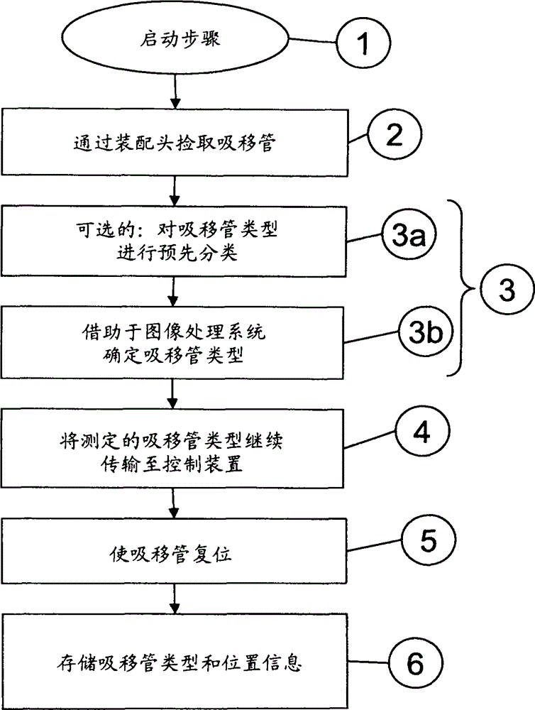
[0023] figure 1 An exemplary flow chart of a method according to the invention for detecting a pipette configuration for an assembly process in an assembly device is schematically shown. Pipettes for assembly of substrates or printed circuit boards are provided in the pipette changer for production. Pipettes with different pipette types are used corresponding to the components to be assembled. The pipette types are distinguished, for example, on the basis of different lengths of the pipettes, different air flows and / or different geometrical features, in particular of the end faces.

[0024] The method according to the invention is carried out prior to assembling the substrate with electronic components. The method according to the invention begins with a start-up step 1 . In a second method step 2, the pipettes arranged in the pipette changer are picked up by the assembly head of the assembly device and mounted on this assembly head.

[0025] In a third method step 3 , the...


PUM


Abstract

The method involves providing different types of pipettes in a pipette exchanging device for assembly of substrates with electronic elements. One of the pipettes is taken out from the exchanging device by an assembling head of an assembling device. Type of each pipette provided in the head is determined by image processing. The determined type of the pipette provided in the head is forwarded to a control device of the assembling device. Information about position of the pipette in the exchanging device is stored together with the determined pipette type.

Description

technical field [0001] The invention relates generally to the field of assembling substrates with electronic components by means of assembly devices. In particular, the invention relates to a method for identifying a pipette configuration in a pipette changer for an assembly process in an assembly device. In the pipette changing apparatus, pipettes having different types of pipettes are provided for assembling the substrate with electronic components. Background technique [0002] In assembly technology, especially in so-called surface mount technology (SMT), components are mounted on the surface of a substrate or printed circuit board by so-called assembly devices (eg automatic assembly machines, assembly modules, etc.). The components to be assembled are brought to the pick-up position by means of so-called feeding devices for the assembly process. For picking and placing components, assembly heads are used in assembly devices that can be moved by positioning systems. I...

Claims


Application Information

Patent Timeline
Patent Type & Authority Patents(China)
IPC IPC(8): H05K13/02H05K13/04
CPCH05K13/0408H05K13/0409
Inventor 卡尔-海因茨·贝施米夏埃尔·布罗特马尔科·特赖贝尔
Owner ASM ASSEMBLY SYST GMBH & CO
Learn More