
Casting guiding device

A guiding device and casting flow technology, applied in the field of metal casting equipment, can solve the problems of high casting speed, poor side bulging effect, easy outward deformation, etc.

Inactive Publication Date: 2011-05-04
CISDI ENG CO LTD
View PDF8 Cites 7 Cited by
  • Summary
  • Abstract
  • Description
  • Claims
  • Application Information

AI Technical Summary

Problems solved by technology

In order to solve this problem, the existing slab casting machine adopts the structure of setting side foot rolls under the crystallizer; but because the side foot rolls are suspended at the lower part of the mold, the rigidity of the support is not enough, and it is easy to deform outwards, which is very difficult to solve the problem of side rolls. Belly ineffective
[0004] Therefore, it is necessary to explore a device that can effectively solve the problem of side bulging of the slab when the continuous casting machine produces the slab, so as to adapt to the higher casting speed and the production of thicker slabs in modern continuous casting production.

Method used


Image

  • Casting guiding device
  • Casting guiding device
  • Casting guiding device

Examples


Embodiment Construction

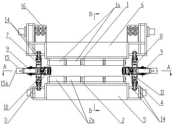
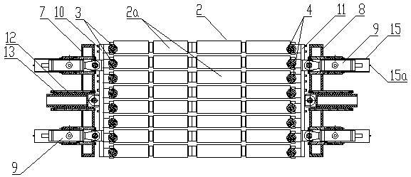
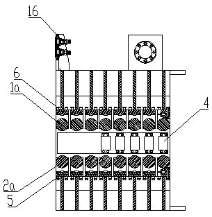
[0022] figure 1 It is a structural schematic diagram of the present invention, figure 2 for figure 1 A-A sectional view of, image 3 for figure 1 B-B sectional view of the figure, as shown in the figure: the casting strand guiding device of this embodiment includes a wide-surface guiding device and a side guiding device, and the wide-surface guiding device includes multiple rows of outer arc wide-surface roller rows 1 arranged side by side along the casting strand direction and the inner arc wide surface roll row 2, the side guide device includes multiple rows of left side rolls 3 and right side rolls 4 arranged side by side along the direction of the casting stream, the outer arc wide surface roll row 1, the inner arc wide surface The roll row 2, the left side roll 3 and the right side roll 4 together form a strand guiding channel. After the slab comes out of the crystallizer, under the restriction of the casting strand guiding channel, even if the casting speed is high a...


PUM


Abstract

The invention discloses a casting guiding device. The device comprises a broadside guiding device and a lateral side guiding device, wherein the broadside guiding device comprises an outer arc broadside roller row and an inner arc broadside roller row which are distributed in parallel along the casting direction; the lateral side guiding device comprises a left lateral side roller and a right lateral side roller which are distributed in parallel along the casting direction; the outer arc broadside roller row, the inner arc broadside roller row, the left lateral side roller and the right lateral side roller together enclose a casting guiding channel; and after a cast blank is out of a crystallizer, under restriction of the casting guide channel, no bump is generated even if the pulling speed is high and the thickness is large. Furthermore, the casting guiding device can accurately adjust the size of the casting guiding channel to adapt to the requirement for producing various cast blanks in different specifications, and can be applied to continuous casting machines for conventional plate blanks and extra thick plate blank.

Description

technical field [0001] The invention relates to metal casting equipment, in particular to a component of a slab continuous casting machine. Background technique [0002] The production process of continuously casting high-temperature molten steel into a billet with a certain cross-sectional shape and a certain size specification is called continuous steel casting, and the equipment required to complete this process is called continuous casting equipment. The electromechanical and hydraulic integration of steel pouring equipment, continuous casting machine body equipment, cutting area equipment, dummy bar collection and conveying equipment constitutes the core equipment of continuous steel casting, which is customarily called continuous casting machine. [0003] The casting stream guiding device of the continuous casting machine is an important part of the continuous casting machine. After the casting slab leaves the mold, the thin slab formed is relatively thin. Under norm...

Claims


Application Information

Patent Timeline
Patent Type & Authority Applications(China)
IPC IPC(8): B22D11/12
Inventor 陈南菲曾珊彭晓华
Owner CISDI ENG CO LTD
Learn More