
Compound burner

A burner and composite technology, applied in the direction of burner, gas fuel burner, combustion method, etc., can solve the problems of high energy consumption, insufficient combustion of gas, etc., and achieve the effect of improving combustion performance and optimizing the combustion environment

Inactive Publication Date: 2011-05-04
周佳强
View PDF0 Cites 0 Cited by
  • Summary
  • Abstract
  • Description
  • Claims
  • Application Information

AI Technical Summary

Problems solved by technology

[0003] In order to effectively utilize energy and solve the problems of insufficient gas combustion and high energy consumption in the direct combustion of gas used in existing burners, the patent of this invention provides a composite energy-saving burner

Method used


Image

  • Compound burner
  • Compound burner
  • Compound burner

Examples


Embodiment Construction

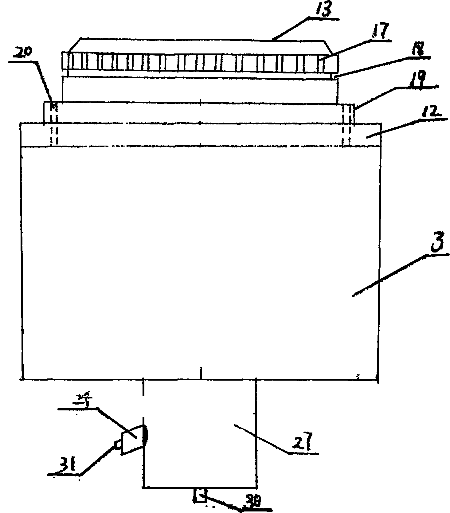
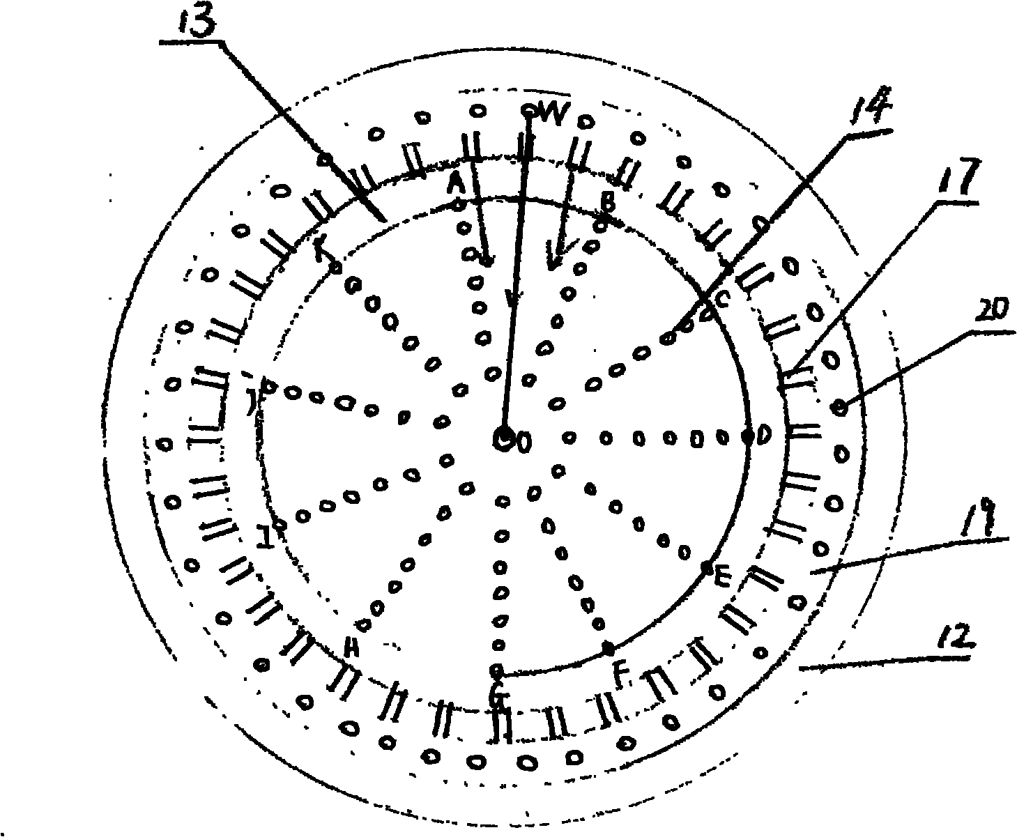
[0015] see figure 1 , figure 2 , image 3 As shown: the patent of the present invention is composed of an inner core 1, an upper cover 2, and a base 3, the inner core 1 is placed on the base 3, the upper end of the base 3 is provided with a protruding ring 11, and the lower end of the inner core 1 is also provided with a protruding ring 12 , the outer diameter of the protrusion 11 at the upper end of the base 3 matches the inner diameter of the collar 12 at the lower end of the inner core 1, so as to ensure that the inner core 1 can be placed firmly on the base 3, and several main combustion chambers are transparently provided on the upper end cover 13 of the inner core 1 The injection hole 14, the inner core 1 is hollow, the hollow part is the upper main gas chamber 15, the lower end of the inner core 1 is the lower main gas chamber 16, and a main gas premixing chamber is arranged between the upper main gas chamber 15 and the lower main gas chamber 16 Partition 28, the mai...


PUM


Abstract

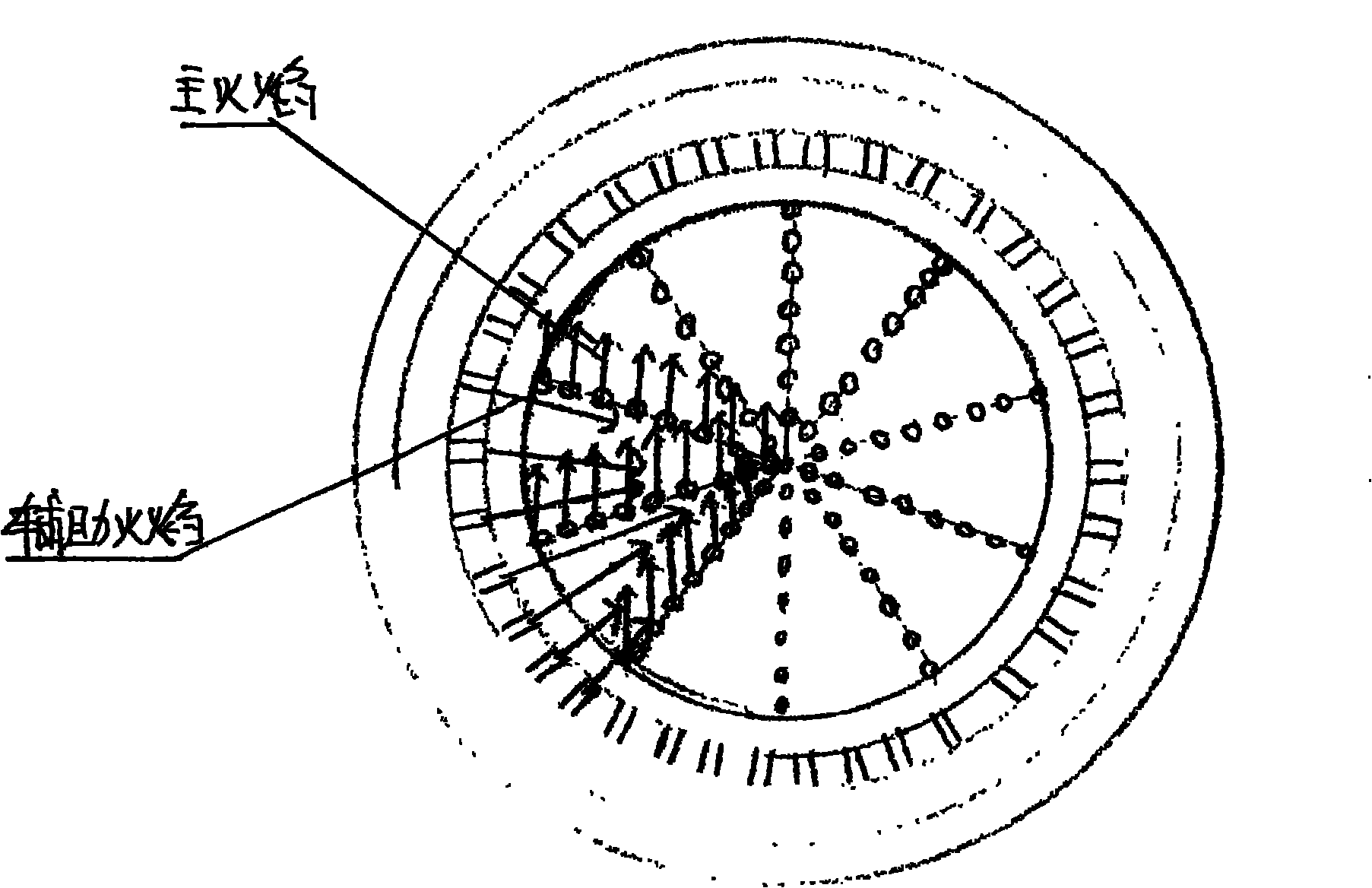
The invention relates to a compound burner characterized by comprising a main burner and an auxiliary burner and being mainly composed of an inner core, an upper cover cap and a base, wherein an upper end cover of the inner core is provided with penetrated main burning nozzle holes which are communicated with an upper and a lower main gas chambers to form the main burner; auxiliary burning nozzle holes are arranged in a circle on the outer wall of the inner core below the upper end cover of the inner core, a circular groove is arranged at the lower ends of the auxiliary burning nozzle holes on the outer wall of the inner core, a circular auxiliary gas premixing spacer is arranged at the lower ends of the inner core and the upper end of a convex ring on the outer wall of the inner core, penetrated auxiliary burning channels are arranged in a circle in the auxiliary gas premixing spacer, the upper cover cap is covered on the inner core and provided with an inwards-inclined surface on the inner wall, an upper auxiliary gas chamber is formed among the inclined surface of the inner wall of the upper cover cap, the outer wall of the inner core part and the groove in the outer wall of the inner core, and the auxiliary burning nozzle holes, the upper auxiliary gas chamber, the auxiliary burning channels and a lower auxiliary gas chamber are communicated to form the auxiliary burner; and a mixed gas input pipeline of the auxiliary burner is sheathed outside a mixed gas input pipeline of the main burner. As shown in figure 4, the main burning nozzle holes are reasonably arranged, so that flame of the auxiliary burner can smoothly flow to the center of main flame from the outer circle in the horizontal direction. The auxiliary flame can uniformly heat the main flame, thereby being a stable fluid flame type diffusing carrier for the main flame. Thus, the main and the auxiliary burning systems have the advantages of high efficiency, energy saving and environment protection.

Description

technical field [0001] The patent of the present invention relates to a composite burner, in particular to a new energy-saving burner. Background technique [0002] At present, the burners used in most gas stoves use the direct combustion method of mixing gas and air to work. The premixed combustible gas used in the burner does not rely on another fire source to ignite and burn. Concentration-related, the mixed direct combustion of gas and air generally has problems such as insufficient combustion, slow combustion reaction speed, and low thermal efficiency, resulting in a great waste of gas and serious energy loss. Invention content: [0003] In order to make effective use of energy and solve the problems of insufficient gas combustion and high energy consumption in the direct combustion of gas used in existing burners, the patent of the present invention provides a composite energy-saving burner. [0004] The composite burner is composed of an inner core, an upper cover,...

Claims


Application Information

Patent Timeline
Patent Type & Authority Applications(China)
IPC IPC(8): F23D14/04F23D14/46F23D14/58F23D14/64
Inventor 周佳强
Owner 周佳强
Learn More