
High-precision digital indicating gauge and adjusting method of position precision of main gate and auxiliary gate

An adjustment method and high-precision technology, which is applied in the field of high-precision digital display indicators and the adjustment of the position accuracy of the main and auxiliary grids, can solve the problems of low production efficiency, inability to adjust, waste of manpower and material resources, etc., to reduce production consumables, The effect of ensuring assembly accuracy and improving production efficiency

Active Publication Date: 2012-09-19
GUILIN GUANGLU MEASURING INSTR CO LTD
View PDF0 Cites 0 Cited by
  • Summary
  • Abstract
  • Description
  • Claims
  • Application Information

AI Technical Summary

Problems solved by technology

[0002] At present, the guide structure of the digital indicator meter for measuring movement generally adopts the coordinated movement of the guide pin and the guide groove. It is difficult or impossible to adjust the position accuracy of the main and auxiliary grids. It is difficult to guarantee the accuracy of the product, resulting in a lot of scrap parts , the production efficiency is low, and a lot of manpower and material resources are wasted

Method used


Image

  • High-precision digital indicating gauge and adjusting method of position precision of main gate and auxiliary gate
  • High-precision digital indicating gauge and adjusting method of position precision of main gate and auxiliary gate
  • High-precision digital indicating gauge and adjusting method of position precision of main gate and auxiliary gate

Examples


Embodiment Construction

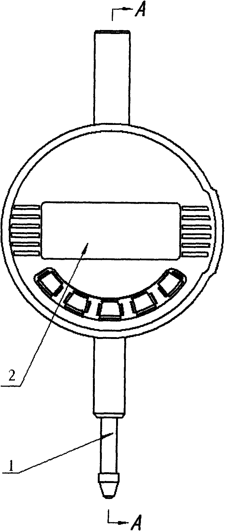
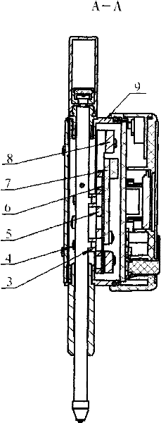
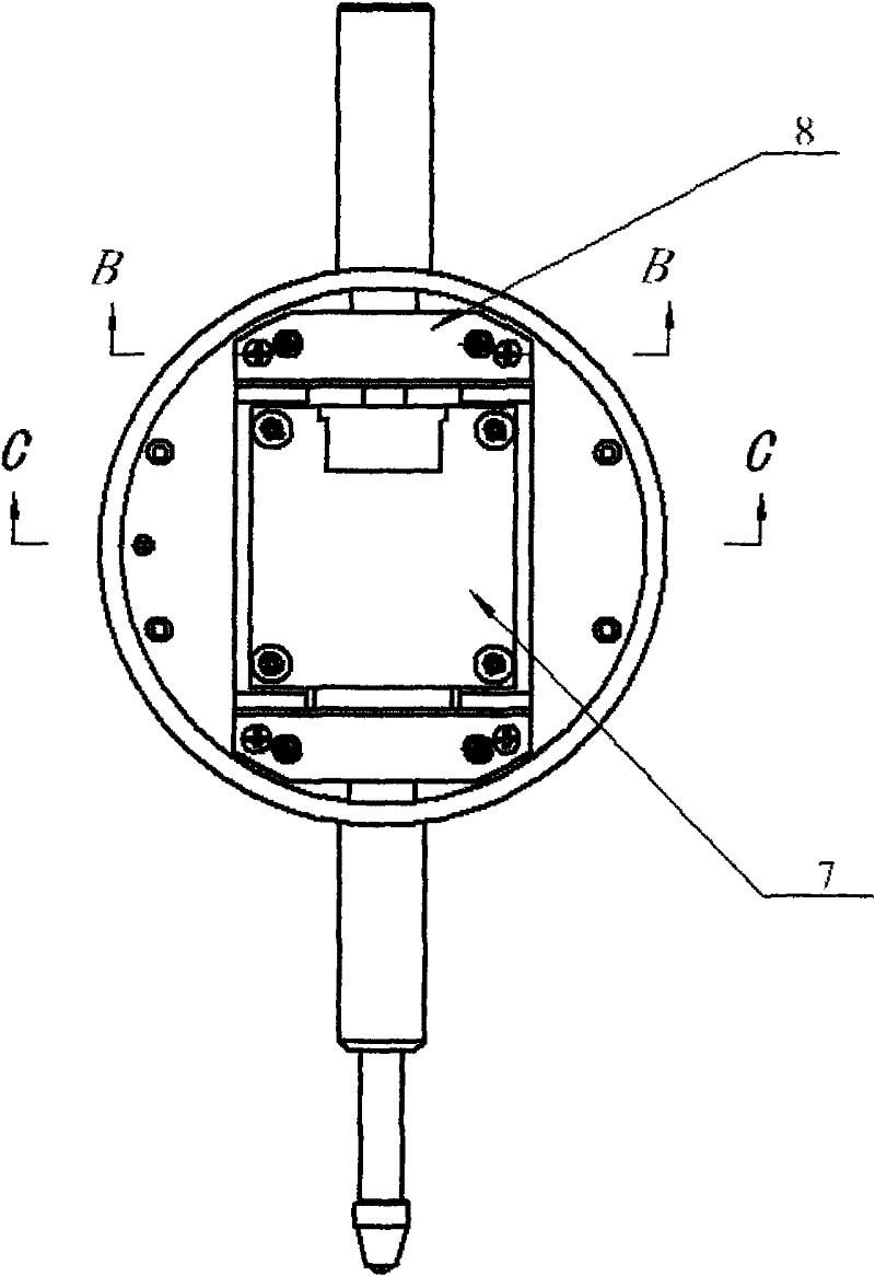
[0013] like figure 1 , figure 2 , Figure 4 , Figure 5 As shown, the measuring rod 1 is slidingly connected with the upper and lower shaft sleeves in the meter body part 9, the display assembly 2 is connected with the upper surface of the meter body in the meter body part 9 with screws, and the lower end of the balance plate 3 is connected to the middle part of the measuring rod 1 Connect with two cross-recessed set screws 4, connect the upper end with the auxiliary grid plate 5 with four connecting screws 12, bond the auxiliary grid 6 with the upper end of the auxiliary grid plate 5, and connect the main grid 7 with the main grid support 8 with screws , the main grid support 8 is connected with the watch body in the watch body part 9 by fastening screws 10 , and the adjustment screw 11 is threadedly connected with the main grid support 8 .

[0014] The adjustment method of the position accuracy of the main and auxiliary grids: the position of the auxiliary grid 6 is unch...


PUM


Abstract

The invention relates to a high-precision digital indicating gauge, belonging to the field of electronic instrument manufacturing and an adjusting method of the position precision of a main gate and an auxiliary gate. The invention is characterized in that a measuring rod is slidingly connected with an upper shaft sleeve and a lower shaft sleeve in a gauge body; a display component is connected with the upper end of the gauge body in a gauge body component in a fastening manner; the lower surface of a balance plate is connected with the middle of the measuring rod by cruciform slot fastening screws, and the upper surface of the balance plate is connected with an auxiliary gate plate by connecting screws; the auxiliary gate is bonded with the upper end surface of the auxiliary gate plate; the main gate is connected with a main gate bracket by screws; the main gate bracket is connected with the gauge body in the gauge body component by fastening screws; and adjusting screws are connected with the main gate bracket. In the invention, the fastening screws and the adjusting screws can be respectively and finely adjusted according to the needs, so that the parallelism and gaps and the like of the main gate and the auxiliary gate reach accurate technical requirements. The invention is applicable to various digital percentage indicating gauges and digital permillage indicating gauges with small specifications.

Description

technical field [0001] The invention relates to a method for manufacturing and assembling an electronic instrument, in particular to a method for adjusting the position accuracy of a high-precision digital display indicator and a main and auxiliary grid. Background technique [0002] At present, the guide structure of the digital indicator meter for measuring movement generally adopts the coordinated movement of the guide pin and the guide groove. It is difficult or impossible to adjust the position accuracy of the main and auxiliary grids. It is difficult to guarantee the accuracy of the product, resulting in a lot of scrap parts , the production efficiency is low, and a lot of manpower and material resources are wasted. Contents of the invention [0003] The purpose of the present invention is to provide a high-precision digital display indicator and a method for adjusting the position accuracy of the main and auxiliary grids, so that the structure of the high-precision ...

Claims


Application Information

Patent Timeline
Patent Type & Authority Patents(China)
IPC IPC(8): G01B3/22
Inventor 董中新李品毅
Owner GUILIN GUANGLU MEASURING INSTR CO LTD
Learn More