Three-dimensional imaging measurement system combining planar array imaging with laser scanning

An area array imaging and measurement system technology, which is applied in the directions of measuring devices, photogrammetry/video metrology, surveying and navigation, etc., can solve the problems of difficult real-time rendering and processing of laser point cloud data, complex calculation formulas, and complex image coordinate formulas and other issues, to achieve real-time fast rendering, save calibration work, and improve the effect of superiority

Inactive Publication Date: 2011-05-04
青岛中科智富光电科技有限公司
View PDF2 Cites 25 Cited by
  • Summary
  • Abstract
  • Description
  • Claims
  • Application Information

AI Technical Summary

Problems solved by technology

Moreover, the formula for calculating the image coordinates corresponding to the laser point cloud is complex, and the conversion of the two coordinate systems in this process requires complex calculations of three rotations and one translation
Th

Method used


Image

  • Three-dimensional imaging measurement system combining planar array imaging with laser scanning
  • Three-dimensional imaging measurement system combining planar array imaging with laser scanning
  • Three-dimensional imaging measurement system combining planar array imaging with laser scanning

Examples


Embodiment 1

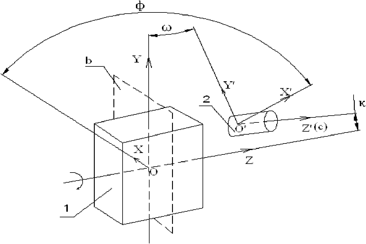
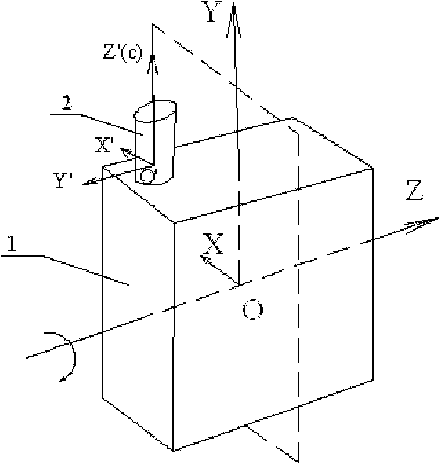
[0037] figure 2 Among them, the scanning surface b of the laser scanning device 1 is vertical to the main optical axis c of the camera A2 of the area array imaging equipment, and the two rotation angles φ and κ are both 0 degrees, which can be completed only after one rotation and one translation transformation The transformations of the two coordinate systems match. The rotation matrix formula can be simplified from formula (1) to formula (3):

[0038] R = R ω = 1 0 0 0 cos ω - sin ω 0 sin ω cos ω ...

Embodiment 2

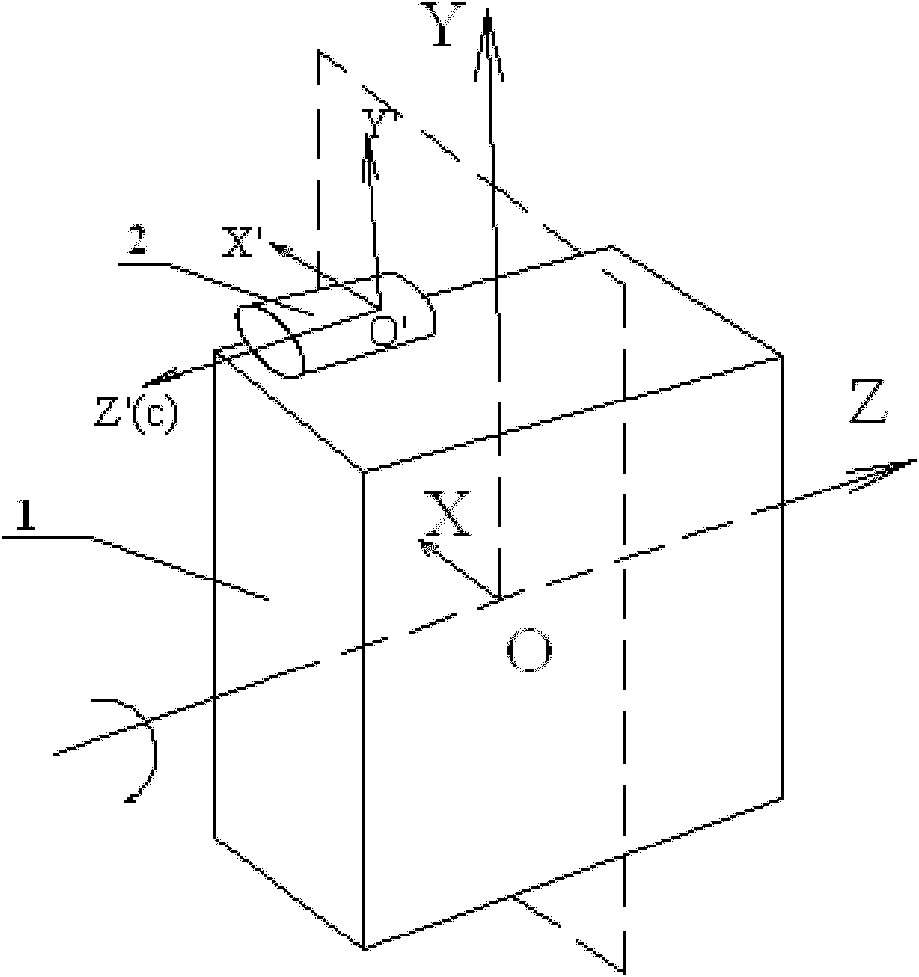
[0044] like image 3 As shown, the laser scanning device 1 is combined with a single area array imaging device camera A2. The laser scanning coordinate system takes the scanning center as the origin 0, the motor rotation axis as the Z axis, and the local coordinate system XYZ established as the Y axis vertically upward; the camera The image space coordinate system obtained by taking pictures is based on the center of the camera image plane as the origin, the horizontal direction along the image plane is the X' axis, the vertical direction is the Y' axis, and the main optical axis is the Z' axis to establish the local coordinate system X'Y 'Z'. The scanning plane b of the laser scanning device 1 is parallel to the main optical axis c of the camera A2 of the area array imaging device, so that the two rotation angles ω and κ are both 0 degrees, so that only one rotation and one translation transformation can be completed The transformations of the two coordinate systems match. ...

Embodiment 3

[0051] like Figure 4 As shown, the laser scanning device 1 is a three-dimensional imaging system combined with the area array imaging equipment camera A2 and the area array imaging equipment camera B3. The scanning coordinate system of the laser scanning device 1 takes the scanning center as the origin O, the motor rotation axis as the Z axis, and the local coordinate system XYZ established as the Y axis vertically upward; the image coordinate system obtained by the camera A2 of the area array imaging device is The center of the camera image plane is the origin, the horizontal direction along the image plane is the X' axis, the vertical direction is the Y' axis, and the main optical axis is the Z' axis to establish the local coordinate system X'Y'Z'. The image space coordinate system obtained by the area array imaging device camera B3 is based on the center of the camera image plane as the origin, the horizontal direction along the image plane is the X" axis, the vertical dir...


PUM


Abstract

The invention relates to a three-dimensional imaging measurement system combining planar array imaging with laser scanning, comprising a laser scanning device and at least one planar array imaging equipment camera installed at the periphery of the laser scanning device, wherein the scanning coordinate system of the laser scanning device is XYZ, and the image coordinate system of the at least one planar array imaging equipment camera is X'Y'Z', and omega and kappa are respectively the space included angles of the image coordinate system and the scanning coordinate system X. The three-dimensional imaging measurement system is characterized in that the optical axis of the at least one planar array imaging equipment camera is spatially vertical to or parallel to the scanning surface of the laser scanning device so that any two space included angle values of the omega and the kappa are zero. In the invention, the spatial geometrical relationship between the image coordinate system and the scanning coordinate system is achieved only by single coordinate rotation and single coordinate conversion, thus the matching computation of laser point cloud data and camera image collection data can be simplified, and the fusion superiority of the laser point cloud data obtained by the scanning device and the image data collected by the cameras can be improved.

Description

technical field [0001] The invention belongs to the technical field of laser scanning imaging, and in particular relates to a three-dimensional imaging measurement system combining area array imaging and laser scanning. Background technique [0002] Laser scanning technology is one of the important means of spatial data acquisition. The laser scanning device obtains the laser point cloud data of the scanning target. Usually, the scanning device is equipped with an area array imaging device such as a camera, and the area array imaging device captures the RGB image data of the scanning target area. The laser point cloud data of the target acquired by the scanning device is a series of coordinate points established in the local coordinate system of the scanning device. The image coordinates of the target in the scanning area collected by the area array imaging device are based on the image coordinates of the area array imaging device. Under the spatial coordinate system, RGB c...

Claims


Application Information

Patent Timeline
IPC IPC(8): G01C11/00
Inventor 张珂殊黄琴华武斌
Owner 青岛中科智富光电科技有限公司
Why Eureka
Try Eureka