Method and device for conveying compressed gas

A gas and compression stage technology, which is used in the field of conveying compressed gas and devices, and can solve problems such as unused

Active Publication Date: 2011-05-04
LEOBERSDORFER MASCHFAB GMBH & CO
View PDF2 Cites 2 Cited by
  • Summary
  • Abstract
  • Description
  • Claims
  • Application Information

AI Technical Summary

Problems solved by technology

The disadvantage here is, in particular, that the energy used for compressing the a

Method used


Image

  • Method and device for conveying compressed gas
  • Method and device for conveying compressed gas
  • Method and device for conveying compressed gas

Examples


Embodiment Construction

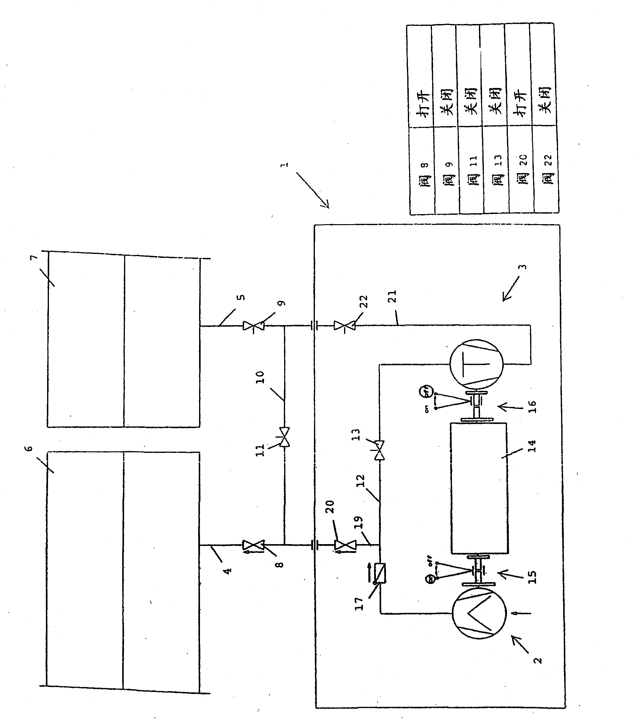
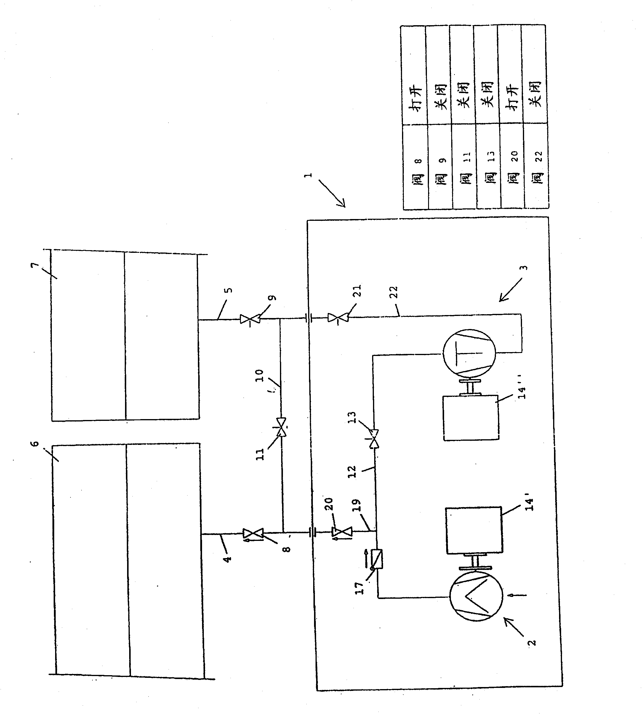
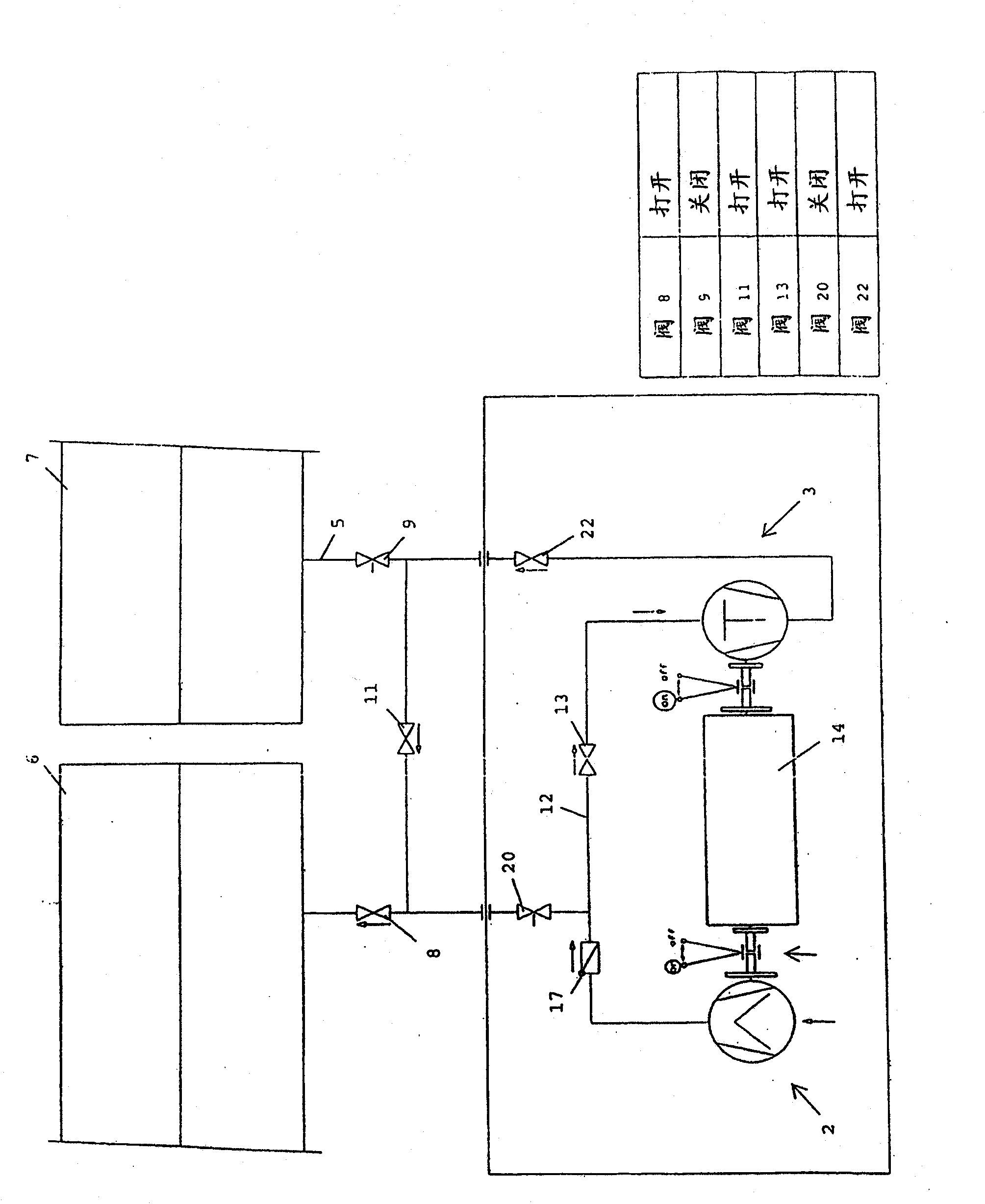
[0028] figure 1 and Figure 1a A compressor 1 with a low-pressure stage 2 and a high-pressure stage 3 is shown in . The compressor 1 is connected via a first gas supply line 4 to a first line section 6 and via a second gas supply line 5 to a second line section 7 . A shut-off valve 8 or 9 is provided in each gas delivery line 4 , 5 so that the intake and exhaust flow through the two gas delivery lines 4 , 5 can be selectively controlled. The two gas supply lines 4 , 5 are connected to one another via a bypass line 10 , which also has a shut-off valve, ie, a bypass valve 11 .

[0029] The two compression stages, ie the low-pressure compression stage 2 and the high-pressure compression stage 3 , are connected to each other via a compression line 12 , in which a shut-off valve, ie, a compression valve 13 , is likewise provided. In the illustrated embodiment, a screw compressor 2 is provided as the low-pressure compression stage 2 and a reciprocating piston compressor is provid...


PUM


Abstract

The invention relates to a method and device for conveying compressed gas into at least two mutually separate pipeline sections (6, 7), wherein gas is compressed and conveyed into a first pipeline section (6), a connection is subsequently produced between the two pipeline sections (6, 7) such that the compressed gas flows from the first pipeline section (6), on account of the excess pressure, into a second pipeline section (7), and gas from the first pipeline section (6) is subsequently compressed and conveyed into the second pipeline section (7).

Description

technical field [0001] The invention relates to a method for conveying compressed gas into at least two mutually separated pipeline sections and a device for conveying compressed gas into at least two mutually separated pipeline sections, said device having at least A compressor, each of which is connected to the pipeline section via a gas delivery pipeline, wherein each of the two gas delivery pipelines has a valve. Background technique [0002] In order to check the tightness of pipelines, especially pipelines, the individual sections are subjected to a pressure test / pressurization test (Abdrücken), i.e. the pipeline section is filled with compressed gas and after a defined period of time it is determined whether the pressure is maintained or A pressure loss occurs. [0003] To this end, conventional gases, in particular air, have hitherto been introduced into a first line section in which a tightness test is carried out, and then the gas, which is usually compressed in t...

Claims


Application Information

Patent Timeline
IPC IPC(8): F04B23/04F04B23/10F04B25/00F04B41/06F04B51/00
CPCF04B23/04F04B23/10F04B25/00F04B41/06F04B49/007F04B51/00
Inventor E·胡塔T·霍因梅塞
Owner LEOBERSDORFER MASCHFAB GMBH & CO
Why Eureka
Try Eureka