Electronic apparatus

A technology of electronic equipment and electro-acoustic transducers, which is applied in the direction of electrical components, telephone structures, sensors, etc., can solve problems such as gaps and sound leakage, and achieve the effects of reliable waterproofing, sound leakage prevention, and distortion prevention

Inactive Publication Date: 2011-05-04
PANASONIC CORP
View PDF6 Cites 7 Cited by
  • Summary
  • Abstract
  • Description
  • Claims
  • Application Information

AI Technical Summary

Problems solved by technology

However, there is a problem that, when the electro-acoustic transducer has a rectangular shape and the membrane member remains circular, a gap occurs between the membrane member and the electro-acoustic transducer, thereby generating sound leakage

Method used


Image

  • Electronic apparatus
  • Electronic apparatus
  • Electronic apparatus

Examples


Embodiment approach

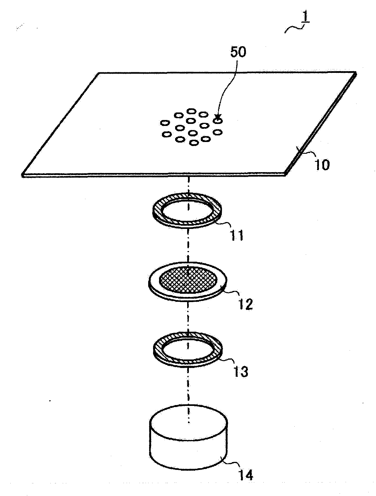
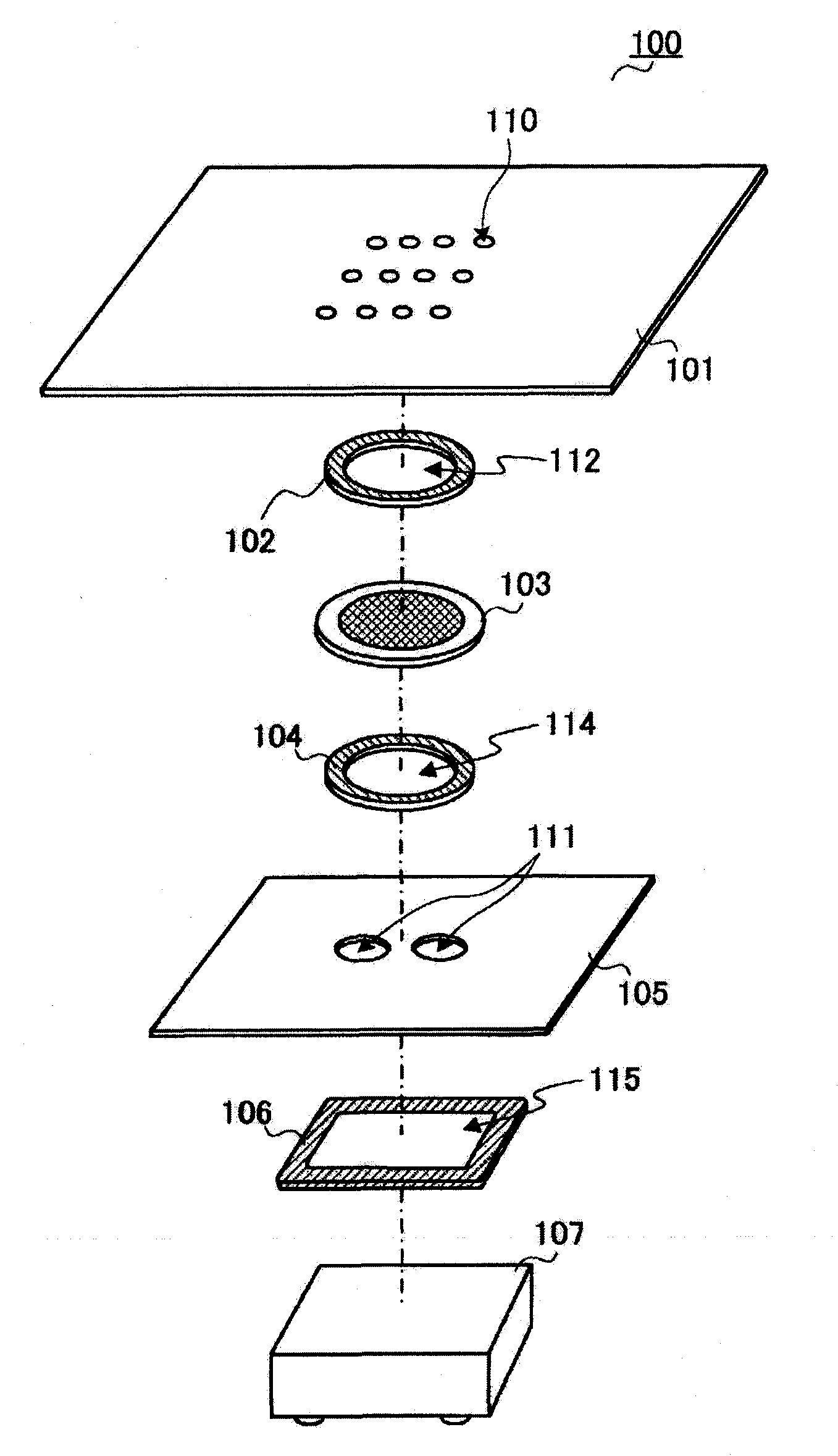
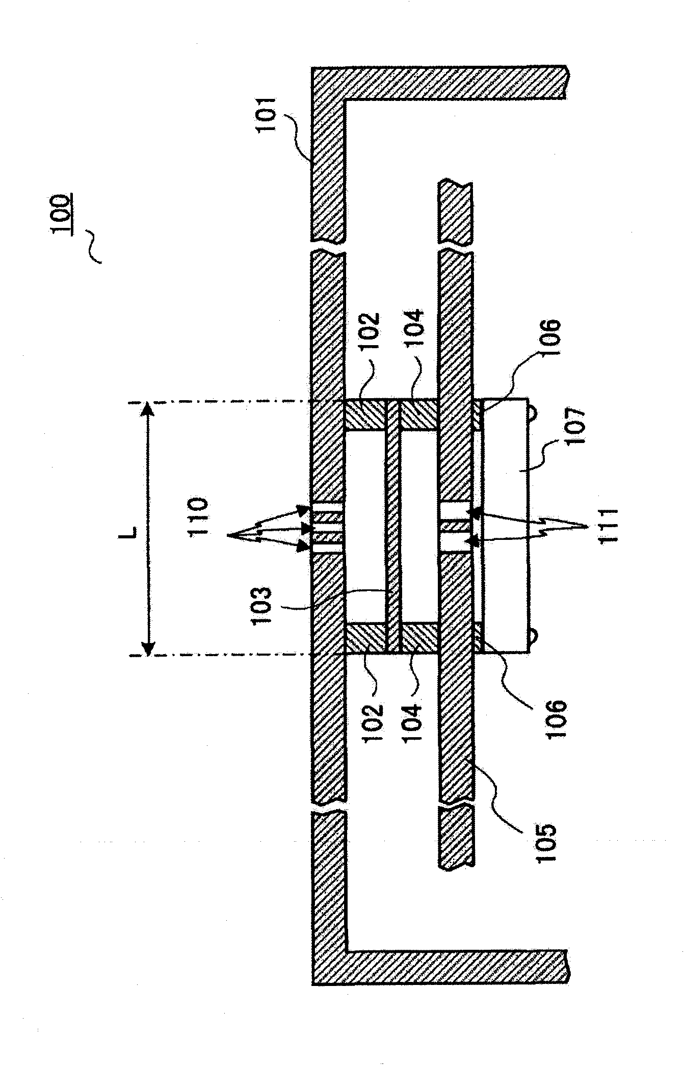
[0024] figure 2 It is an exploded perspective view of main parts of the electronic device 100 according to the embodiment of the present invention.

[0025] The electronic device 100 is mainly composed of a first case 101 , a buffer member 102 , a film member 103 , a buffer member 104 , a plate member 105 , a buffer member 106 , and an electroacoustic transducer 107 . Electronic device 100 is, for example, a communication terminal device such as a mobile phone or a portable television. In addition, the buffer member 102, the film member 103, the buffer member 104, the plate-shaped member 105, the buffer member 106, and the electroacoustic transducer 107 are housed in another case and the second case described later that are composed of a single body with the first case 101. 1 The inner space formed by the casing 101. But when figure 2 In , only a part of the first housing 101 is described, and the description of other housings is omitted.

[0026] The first housing 101 h...


PUM


Abstract

Disclosed is an electronic apparatus which can ensure waterproofness or dustproofness when a rectangular electroacoustic transducer is employed, and can prevent both distortion of voice and leakage of sound at the same time. A first casing (101) of the electronic apparatus has sound holes (110). A film member (103) is substantially circular and provided between the sound holes (110) and an electroacoustic transducer (107). A planar member (105) is provided between the film member (103) and the electroacoustic transducer (107) and has second sound holes (111). The electroacoustic transducer (107) is substantially rectangular and generates voice.

Description

technical field [0001] The present invention relates to electronic equipment, for example, to electronic equipment in which an electroacoustic transducer (electroacoustic transducer) provided inside a housing is waterproofed. Background technique [0002] Conventionally, there is known a telephone provided with a waterproof membrane for waterproofing acoustic components (for example, Patent Document 1). [0003] figure 1 It is an exploded perspective view of a main part of a conventional electronic device 1 such as a telephone. A conventional electronic device 1 is mainly composed of a case 10 , a cushion member 11 , a membrane member 12 , a cushion member 13 , and an electroacoustic transducer 14 . [0004] The casing 10 has a plurality of sound holes 50 as through holes. The sound hole 50 outputs the sound generated from the electro-acoustic transducer 14 to the outside of the housing 10 . [0005] The buffer member 11 is provided between the housing 10 and the membran...

Claims


Application Information

Patent Timeline
Patent Type & Authority Applications(China)
IPC IPC(8): H04R1/00H04M1/02
CPCH04M1/03H04M1/18H04R1/028H04R1/086H04R2499/11
Inventor 德田达彦木村友哉佐田晃康
Owner PANASONIC CORP
Why Eureka
Try Eureka