Staggered supporting wheel type crawler device

A technology of rollers and tracks, which is applied in the field of off-road vehicles, can solve the problems of easy slippage of the transmission rollers, inability to travel smoothly, and tension changes, and achieve the effects of low power consumption, prevention of tension changes, and reduction in amplitude.

Inactive Publication Date: 2011-05-11
孙继华
View PDF0 Cites 1 Cited by
  • Summary
  • Abstract
  • Description
  • Claims
  • Application Information

AI Technical Summary

Problems solved by technology

One of the defects is: when encountering a vertical wall obstacle, the crawler is lifted up by the obstacle in the gap between the two supporting wheels, forming a semi-enclosed state to the obstacle, and the obstacle's jacking on the track causes the track to bulge upward, and the tension of the track It is transmitted to the tensioning wheel, causing tension changes and increasing power consumption. Another major defect is that when the track is lifted by an obstacle and protrudes upward, the multiple rollers rolling on the track will sequentially start from the lowest level of the obstacle. The number of times the obstacle is climbed depends on the number of rollers that climb over the obstacle. Every time the rollers climb over the obstacle, it will consume approximately the same additional power consumption
The current crawler rolling device still has some defects: for example, due to the change of the tension of the crawler belt, the crawler belt will change in tightness when it is moving, and it is difficult to be made into an arc-shaped rolling device that touches the ground.
Another example: If the track falls off the rollers, the smaller number of rollers will usually sink into the soil under the weight. The subsidence of the supporting rollers in the soil, and at the same time, due to the small number of driving rollers, it is easy to slip and cannot move smoothly

Method used


Image

  • Staggered supporting wheel type crawler device
  • Staggered supporting wheel type crawler device
  • Staggered supporting wheel type crawler device

Examples


Embodiment Construction

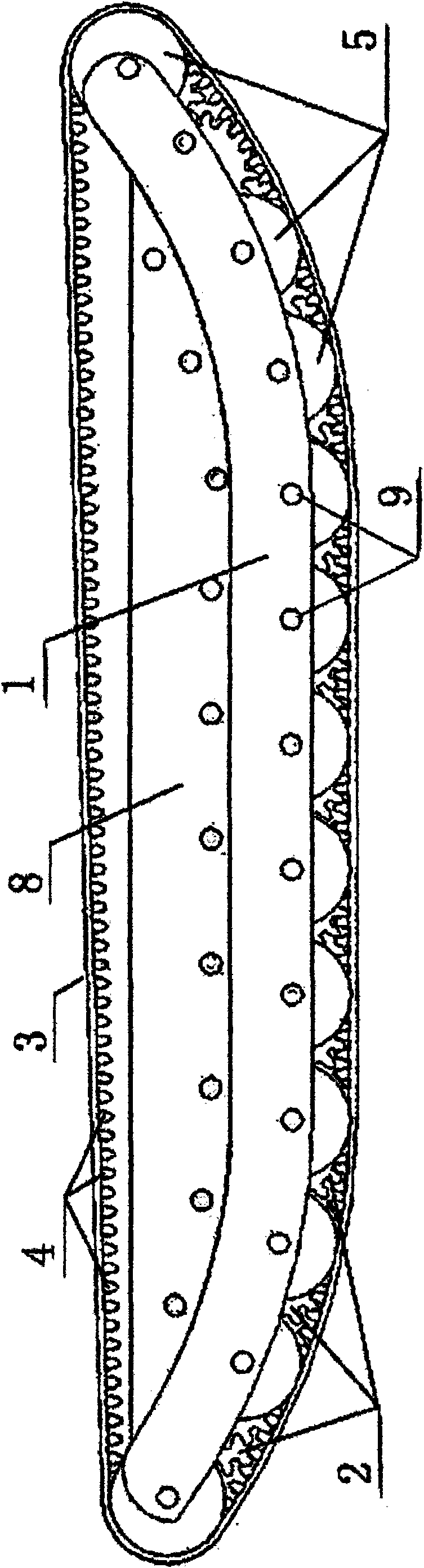
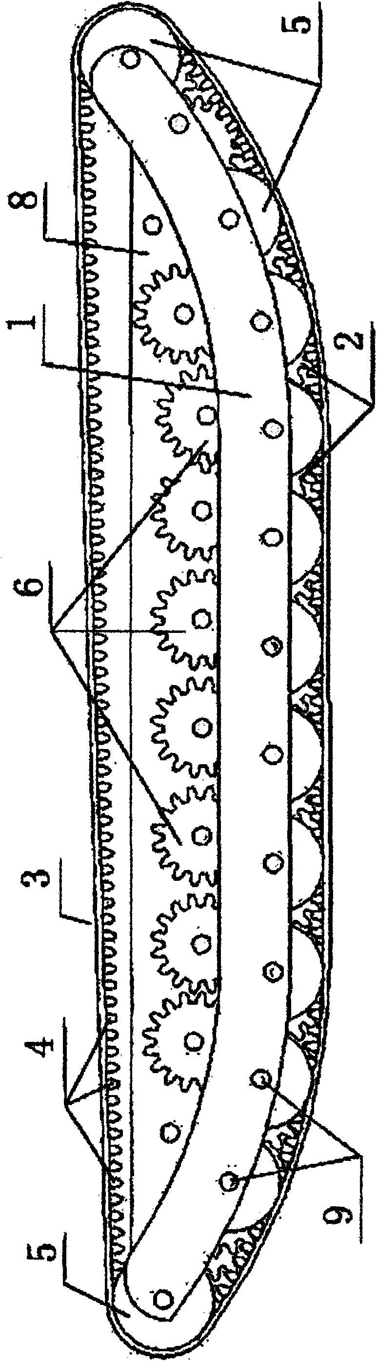
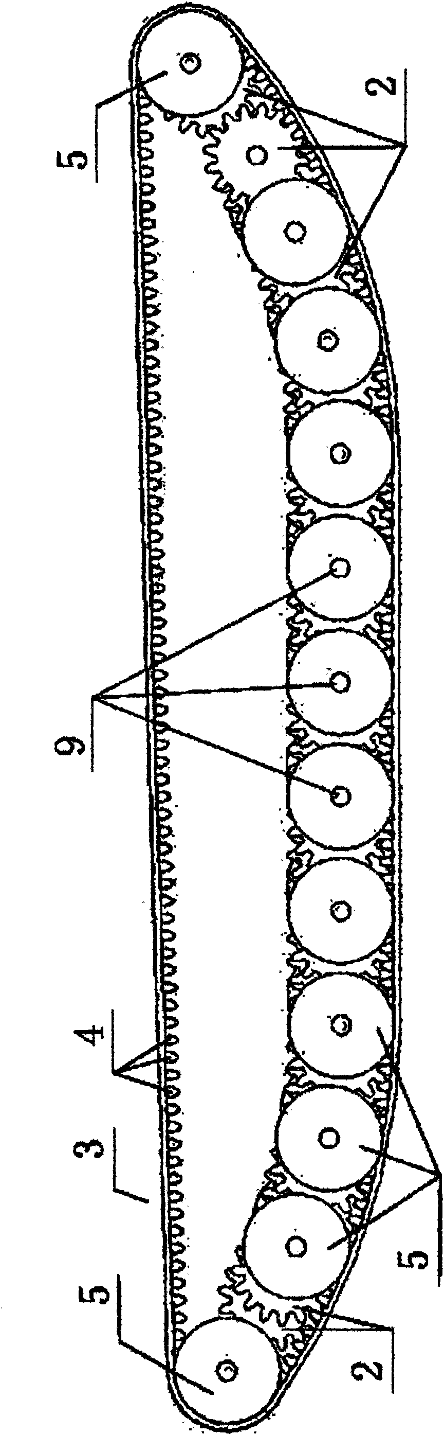
[0016] Combine below figure 1 , figure 2 , image 3 , Figure 4 , Figure 5 , Image 6 One of the embodiments will be described in detail. This embodiment is a staggered roller crawler type rolling device, which consists of a wheel bridge (1), toothed rollers (2), crawlers (3), crawler teeth (4), and a guide pulley (5). ), a transmission gear (6), a transmission gear frame (8), a wheel shaft (9) and other parts. The bridge wheel frame (1) is made into an arc shape at both ends and a flat-bottomed boat shape in the middle. The arc radius of the wheel bridge frame (1) is set according to the off-road requirements of the crawler rolling device, and the length of the flat bottom can be set according to the The crawler rolling device is set according to the requirements of the trench capacity. The toothed rollers (2) are in the shape of gears, and the four rows of toothed rollers (2) are fixed on the wheel bridge (1) through the axles (9), and one row of toothed rollers (2) As t...


PUM


Abstract

The invention relates to a staggered supporting wheel type crawler device, which comprises supporting wheels, a wheel bridge frame, a crawler and idler pulleys, wherein the supporting wheels can be dentiform supporting wheels, a plurality of rows of supporting wheels are arranged on the wheel bridge frame in a staggered way, and the projections of wheel arch profiles are intersected; the wheel bridge frame has an arc shape or a ship shape with two arc-shaped ends and a flat middle; the crawler annularly covers the supporting wheels of the wheel bridge frame, and can be provided with horizontally arranged crawler strip teeth; the crawler strip teeth are matched with the dentiform supporting wheels; and the inner side walls of the idler pulleys roll on two-end sections of the crawler strip teeth in an attaching mode to realize the fixing and guiding functions. The plurality of groups of dentiform supporting wheels are arranged in the staggered way and the crawler strip teeth are adopted, so the tension change of the crawler when the crawler meets an obstacle is effectively controlled. The crawler can be made into an arc-shaped crawler. After the crawler is removed, multi-wheel driven dentiform supporting wheels can disperse pressure to the maximum and also keep high grip performance and sink resistance.

Description

Technical field: [0001] The present invention relates to off-road vehicles, in particular to crawler-type rolling devices. Background technique: [0002] The current crawler device has some major defects. One of the shortcomings is that when encountering a vertical wall obstacle, the track is pushed up by the obstacle in the gap between the two supporting wheels, forming a semi-enclosed state to the obstacle, and the obstacle on the support of the track causes the track to bulge upward, and the tension of the track It is transmitted to the tension wheel, causing tension changes and increasing power consumption. Another major defect is: when the track is supported by obstacles and bulges upward, the multiple support rollers rolling on the track will sequentially descend from the lowest obstacle. The number of obstacles to be overcome depends on the number of support wheels that are used to overcome the obstacle. Each time the support wheels over the obstacle will consume approxim...

Claims


Application Information

Patent Timeline
Patent Type & Authority Applications(China)
IPC IPC(8): B62D55/10
Inventor 孙继华
Owner 孙继华
Why Eureka
Try Eureka