Method and system for controlling an engine using in-cylinder pressure sensor signals

A technology for controlling system and cylinder pressure, applied in machines/engines, internal combustion piston engines, combustion engines, etc., can solve problems such as low calorie level resolution, high signal noise, etc.

Inactive Publication Date: 2011-05-11
GM GLOBAL TECH OPERATIONS LLC
View PDF5 Cites 4 Cited by
  • Summary
  • Abstract
  • Description
  • Claims
  • Application Information

AI Technical Summary

Problems solved by technology

However, it is difficult to resolve the low level of heat released during the HCCI exhaust ga...

Method used


Image

  • Method and system for controlling an engine using in-cylinder pressure sensor signals
  • Method and system for controlling an engine using in-cylinder pressure sensor signals
  • Method and system for controlling an engine using in-cylinder pressure sensor signals

Examples


Embodiment Construction

[0048] The following description is merely exemplary in nature and is not intended to limit the invention, its application or uses in any way. For purposes of clarity, the same reference numbers will be used in the drawings to refer to like elements. As used herein, the phrase at least one of A, B, and C should be construed to mean a logical "A or B or C," where a non-exclusive logical or is used. It should be understood that steps within a method may be executed in different order without altering the principles of the present invention.

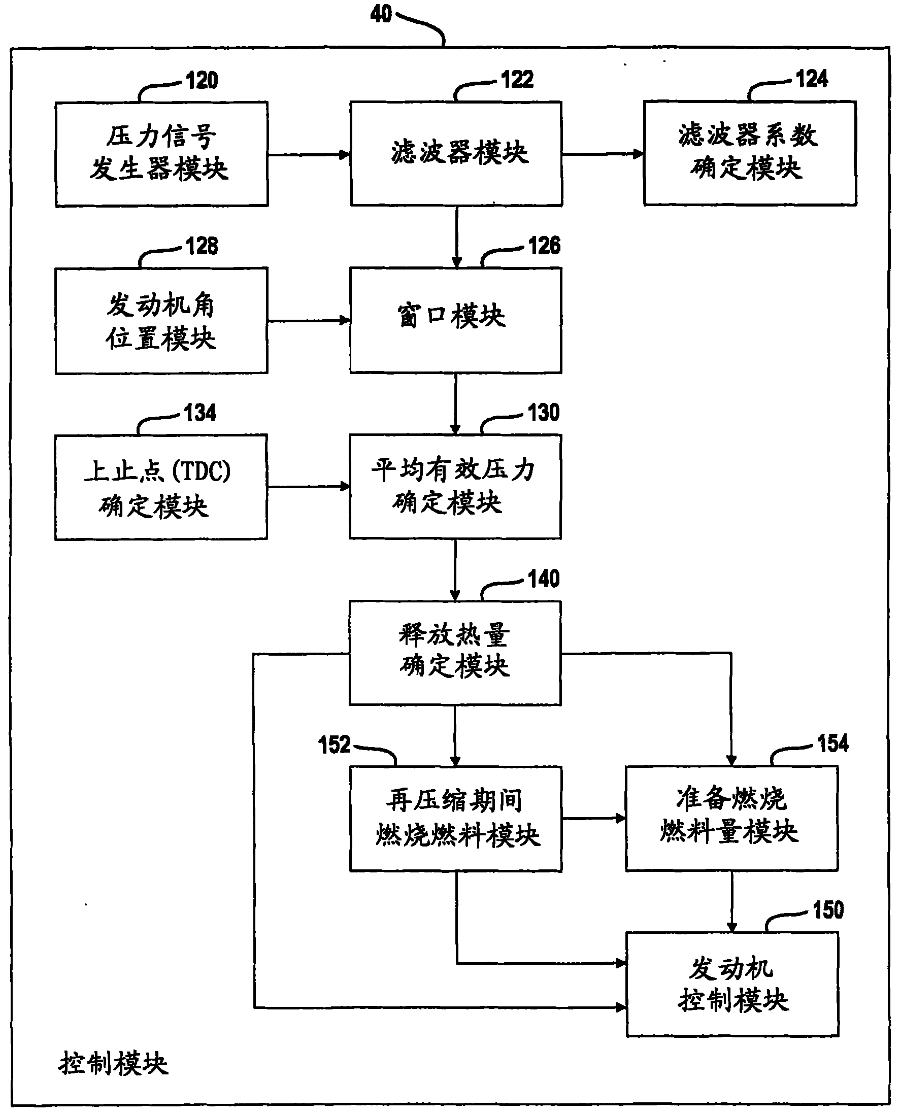
[0049] As used herein, the term "module" refers to an application-specific integrated circuit (ASIC), an electronic circuit, a processor (shared processor, dedicated processor, or group processor) and memory, a combination of Logic circuits and / or other suitable components that provide the described functionality.

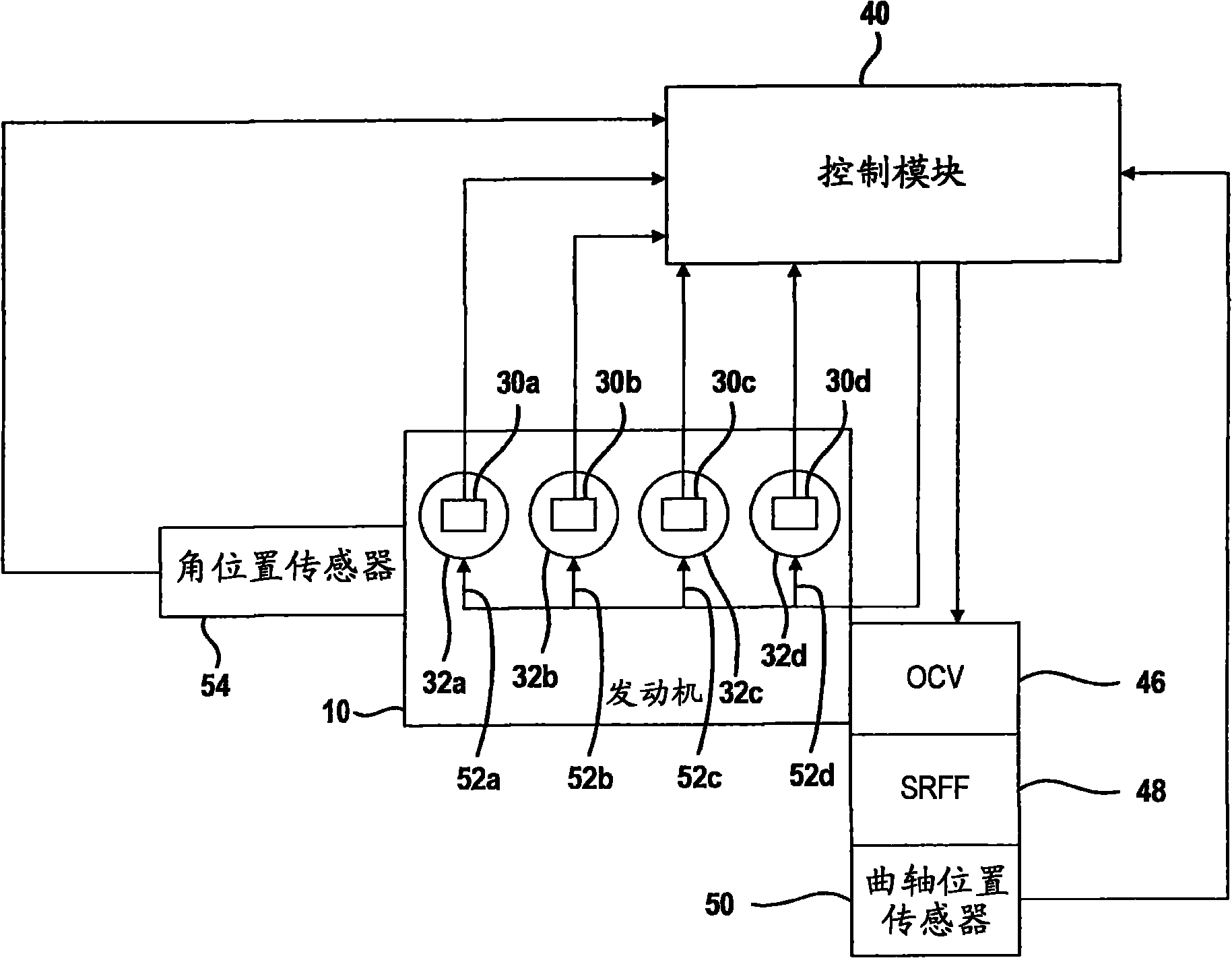
[0050] now refer to figure 1 , engine 10 may include in-cylinder pressure sensors 30A, 30B, 30C, and 30D located within e...


PUM


Abstract

A method and a control system that includes a window module that determines a piston position window, a mean effective pressure determination module that generates a mean effective pressure with in-cylinder pressure signals within the piston position window and an engine control module that controls the engine using the mean effective pressure.

Description

technical field [0001] The present invention relates generally to methods and systems for controlling an engine, and more particularly, to methods and systems for controlling an engine using an in-cylinder pressure sensor signal. Background technique [0002] The background description provided herein is for the purpose of generally presenting the context of the disclosure. The work of the presently named inventors, to the extent described in this Background section and in respect of those described aspects which may not be prior art at the time of filing, is neither expressly nor impliedly admitted to be relative to the present invention existing technology. [0003] An in-cylinder pressure sensor is a type of sensor that can be used in vehicles. In-cylinder pressure sensors provide feedback for operating the engine. The in-cylinder pressure sensor signal may have a significant amount of noise. Low-pass filtering with a band-pass filter may distort the signal to unaccep...

Claims


Application Information

Patent Timeline
IPC IPC(8): F02D45/00
CPCF02D35/023F02D41/3035F02D2250/14Y02T10/12
Inventor K·J·巴斯勒普D·R·维尔纳
Owner GM GLOBAL TECH OPERATIONS LLC
Why Eureka
Try Eureka