Scroll compressor

A scroll compressor and compression chamber technology, applied in rotary piston machinery, rotary piston pumps, mechanical equipment, etc., can solve the problems of reducing the number of scrolls, lack of pressure, residual gas, etc. The effect of improving compression efficiency

Inactive Publication Date: 2011-05-11
HITACHI APPLIANCES INC
View PDF9 Cites 13 Cited by
  • Summary
  • Abstract
  • Description
  • Claims
  • Application Information

AI Technical Summary

Problems solved by technology

[0007] During overcompression, the high-pressure refrigerant can be released from the bypass hole. However, when the refrigerant passes through the bypass hole, a loss called discharge pressure loss that is inversely proportional to the cross-sectional area of ​​the bypass hole will occur.
When the bypass hole is enlarged to reduce the discharge pressure loss, the residual gas problem described later will occur.
In addition, if the discharge port is enlarged in order to reduce the discharge pressure loss, the number of wraps of the scroll will be reduced, and the required pressure cannot be obtained.

Method used


Image

  • Scroll compressor
  • Scroll compressor
  • Scroll compressor

Examples


Embodiment Construction

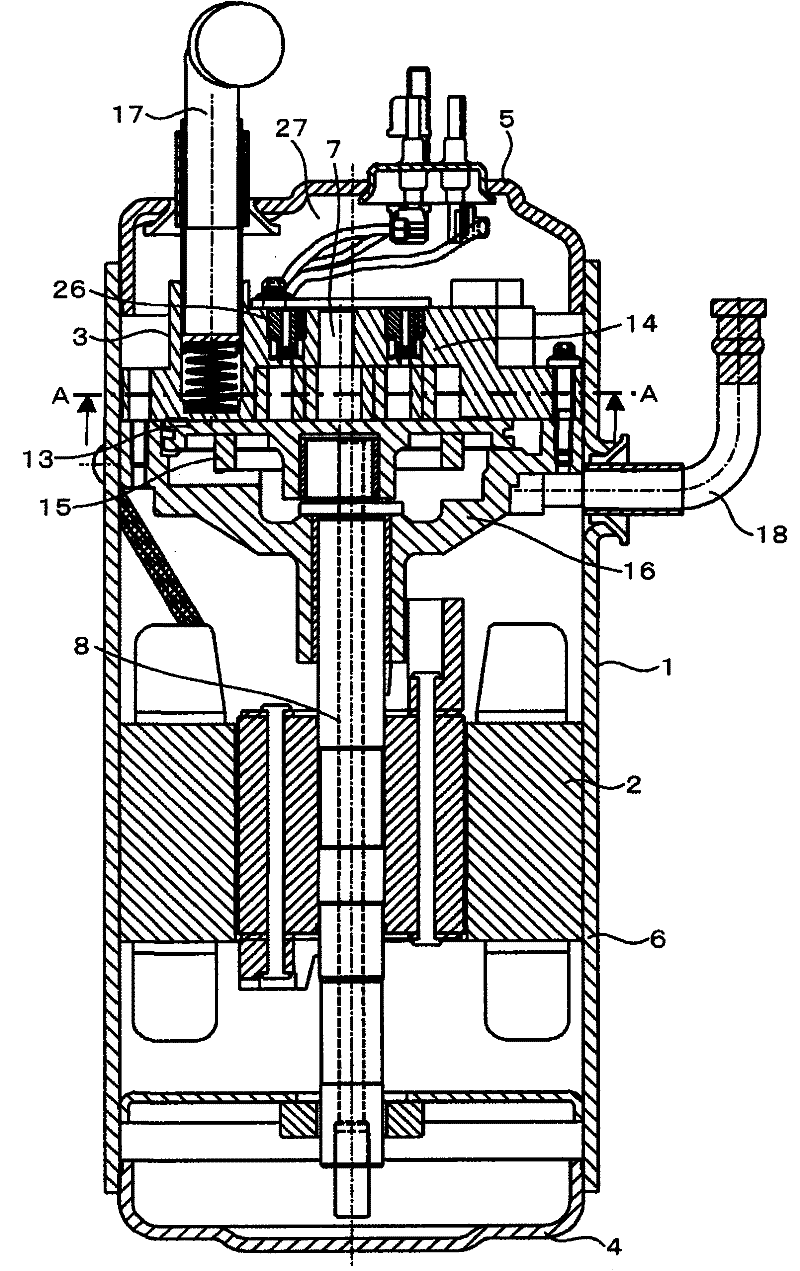
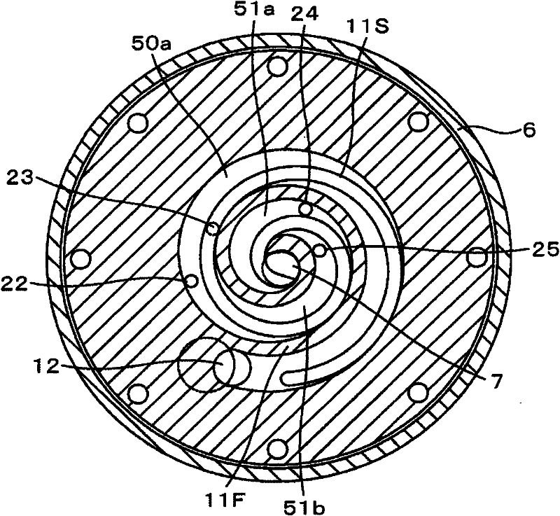
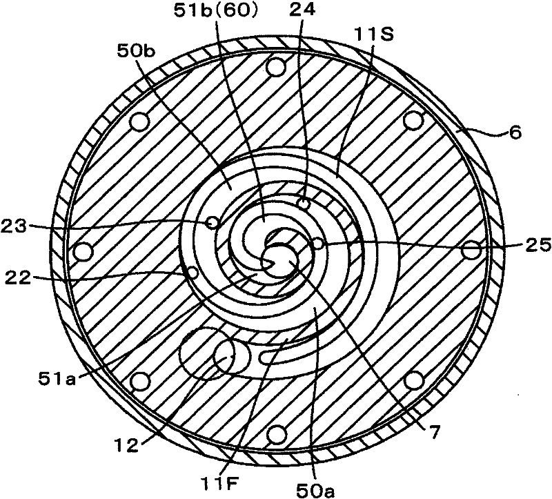
[0059] Below, refer to Figure 1 ~ Figure 3 One embodiment of the present invention will be described.

[0060] figure 1 It is a sectional view of a vertical scroll compressor. As the main structure, a mixed refrigerant of at least one or more than two kinds of fluorinated hydrocarbon-based refrigerants is used as a refrigerant, and a motor 2 and a motor driven by the motor 2 are arranged inside the airtight container 1. The scroll compression mechanism 3 that compresses the mixed refrigerant between the orbiting scroll 13 and the fixed scroll 14 also has an Oldham ring 15 inside the airtight container 1 as an anti-rotation component. The orbiting scroll 13 is supported and guided between the scroll 14 and the fixed member 16 so that the orbiting scroll 13 orbits relative to the fixed scroll 14 without rotating.

[0061] The compression mechanism 3 is formed by meshing a fixed scroll 13 and an orbiting scroll 14 . The orbiting scroll 14 receives the rotation of the motor 2...


PUM


Abstract

During the over-compression, high pressure refrigerant is released from a bypass hole. The sprayed pressure loss in inverse proportion to the cross section of the bypass hole is generated when the refrigerant passes through the bypass hole.The aim of the invention is to improve the compression efficiency of the over-compression region.The invention provides a scroll compressor equipped with two venting valve gears.The two venting valve gears are respectively arranged in two compression chambers closest to an ejection opening.The two compression chambers are paired chambers with respect to a voluted center.The two venting valve gears are arranged in an asynmmetric configuration with respect to the voluted center.At least one of the venting valve gears communicates with the injection outlet when the two compression chambers are under the following two states: one state is that the two compression chambers is about to communicate with the injection outlet; the other state is that the two compression chambers progress 180 degree and communicate with the injection outlet.

Description

technical field [0001] The present invention relates to a scroll compressor used in refrigerating and air-conditioning equipment and the like. Background technique [0002] In the past, in scroll compressors with low vibration and low noise characteristics, the suction chamber was located at the outer periphery of the coil forming the compression space, and the discharge port was located at the center of the coil, and the suction volume and the final compression chamber volume The determined volume ratio is fixed. In particular, when the variation in the compression ratio determined by the suction pressure and the discharge pressure is small, high-efficiency compression can be performed without using a discharge valve device by setting a volume ratio corresponding to it. In reciprocating compressors and rotary compressors, a blowout valve arrangement is required. [0003] When the scroll compressor is used as a refrigerant compressor for refrigerating and air-conditioning ...

Claims


Application Information

Patent Timeline
Patent Type & Authority Applications(China)
IPC IPC(8): F04C18/02
CPCF04C18/0215F04C18/0269F04C23/008F04C28/26F04C29/124F04C2210/26F04C2240/30Y10S415/00Y10S417/902
Inventor 村上晃启岛田敦藤村和幸田所哲也新村修平
Owner HITACHI APPLIANCES INC
Why Eureka
Try Eureka