Lens module

A lens module and lens holder technology, applied in the field of optical systems, can solve the problems of instability, uneven torque/torque, difficulty in accurately adjusting the relative position of the lens barrel and the lens holder, etc., to achieve accurate focusing, uniform locking force, To achieve the effect of focusing

Inactive Publication Date: 2011-05-11
HONG FU JIN PRECISION IND (SHENZHEN) CO LTD +1
View PDF5 Cites 4 Cited by
  • Summary
  • Abstract
  • Description
  • Claims
  • Application Information

AI Technical Summary

Problems solved by technology

However, the engagement force between the thread of the lens mount and the lens barrel and the different threads may be different, resulting in uneven torque / torsion between the lens barrel and the lens mount when the lens barrel is screwed into or out of the lens mount. Stable, it is difficult to accurately adjust the relative position between the lens barrel and the lens mount to achieve accurate focus

Method used


Image

  • Lens module
  • Lens module
  • Lens module

Examples


Embodiment Construction

[0012] The present invention will be further described in detail below in conjunction with the accompanying drawings.

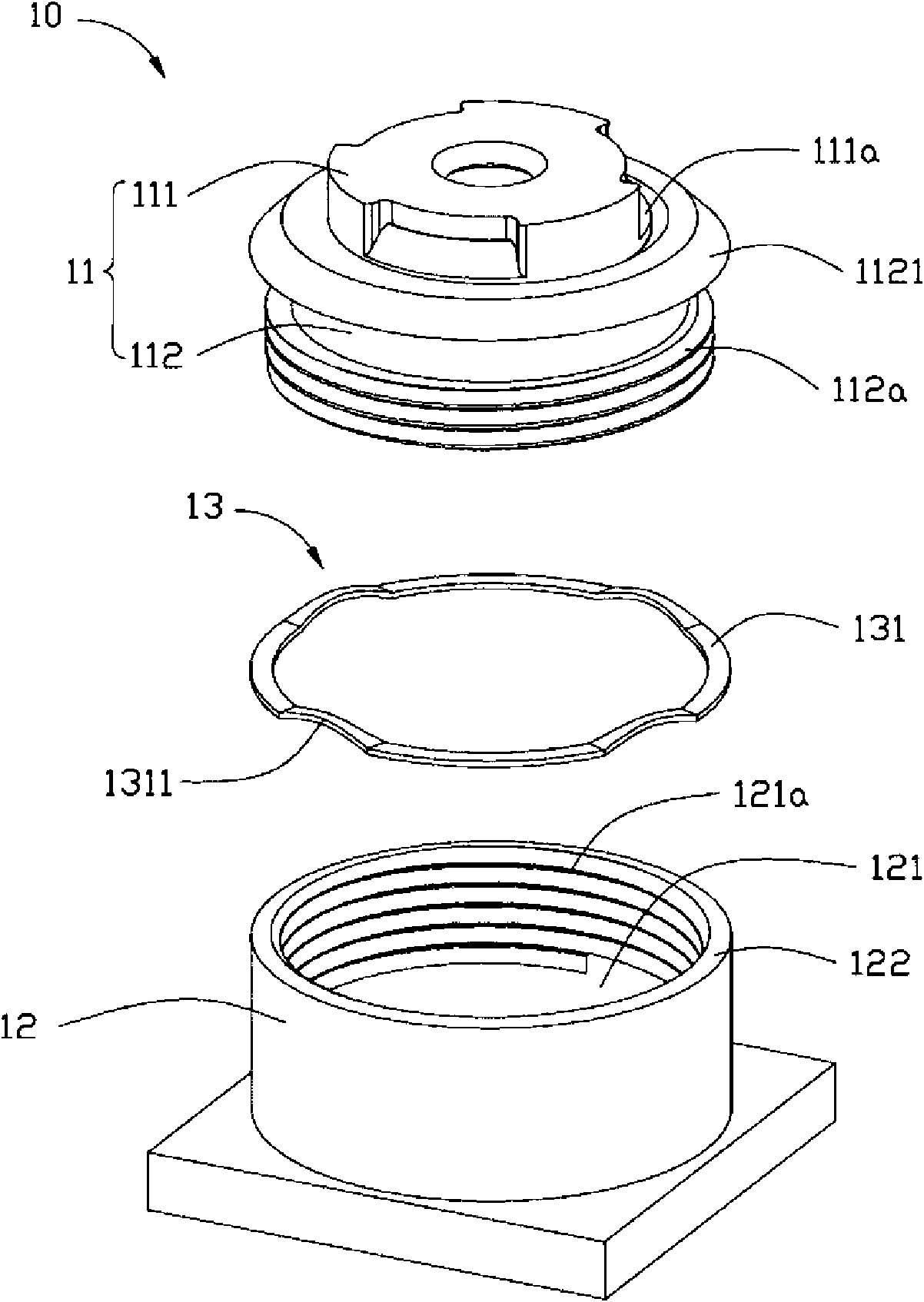
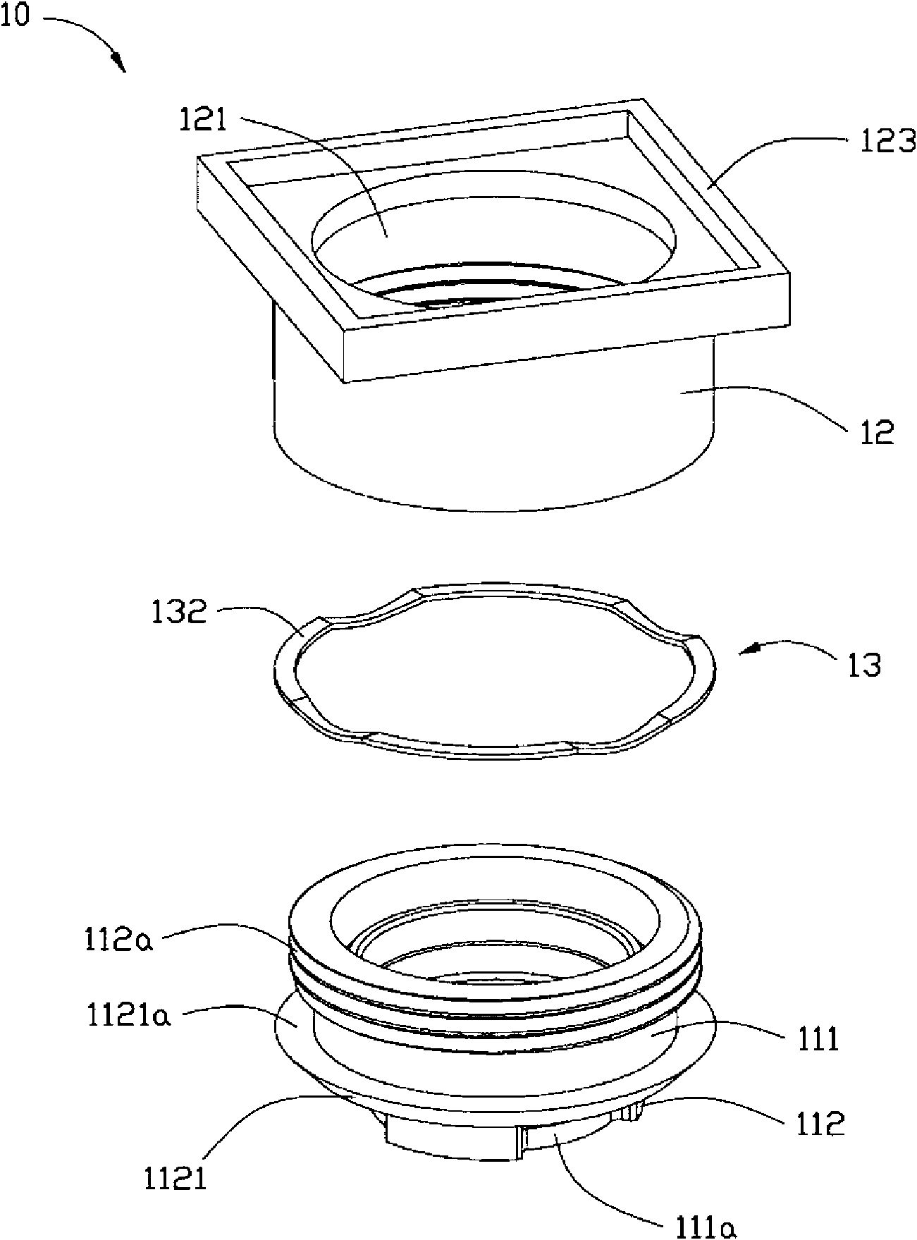
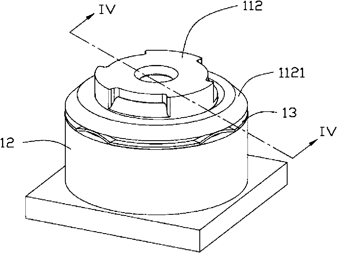
[0013] Such as Figure 1 to Figure 4 As shown, a lens module 10 provided by a preferred embodiment of the present invention includes a lens barrel 11 , a lens mount 12 and an elastic element 13 .

[0014] The inside of the lens barrel 11 accommodates elements such as a lens group, a spacer ring, and a filter (not shown in the figure). The lens barrel 11 sequentially includes an actuating part 111 and a connecting part 112 from the object side to the image side. A plurality of grooves 111 a are evenly spaced on the edge of the actuating part 111 , and the grooves 111 a are used to facilitate rotation of the actuating part 111 . The connecting portion 112 is cylindrical and coaxially connected with the actuating portion 111 . One end of the connecting portion 112 adjacent to the actuating portion 111 forms a crimping portion 1121 , and a crimping surface 112...


PUM


Abstract

The invention relates to a lens module comprising a lens cone, a lens base and an annular elastic element. The lens cone comprises an actuation part and a connection part which are coaxially connected with each other, one end of the connection part, adjacent to the actuation part, is provided with a compression joint part, a compression joint face is formed on one side of the compression joint part towards the lens base, and an outer threaded part is formed on the outer side of the connection part. The lens base is provided with a through hole for accommodating the lens cone, the lens base comprises an upper end face facing one end on the objective side of the lens module, and the inner surface of the through hole is provided with an inner threaded part in loose fit with the outer threaded part. The elastic element is provided with a plurality of arched protrusions along the axial direction of the elastic element and is arranged on the upper end face of the lens base, and the compression joint face of the lens cone abuts against the plurality of arched protrusions. In the invention, the elastic element is adopted for the lens module so that the locking and adhesion force between the lens cone and the lens base is uniform, the relative position between the lens cone and the lens base can be stably and accurately adjusted, and accurate focusing can be realized.

Description

technical field [0001] The invention relates to an optical system, in particular to a lens module. Background technique [0002] With the development of camera technology, lens modules are widely used in camera devices for various purposes. A traditional lens module generally includes a lens base, a lens barrel screwed to the lens base, a lens group, a spacer ring, an optical filter and the like accommodated in the lens barrel. When focusing, generally by turning the focusing ring on the lens barrel, the lens barrel is screwed into or out of the lens holder to adjust the distance between the lens group and the image sensor to obtain a better imaging effect. However, the engagement force between the thread of the lens mount and the lens barrel and different threads may be different, resulting in uneven torque / torque between the lens barrel and the lens mount when the lens barrel is screwed into or out of the lens mount. Stable, it is difficult to accurately adjust the relat...

Claims


Application Information

Patent Timeline
Patent Type & Authority Applications(China)
IPC IPC(8): G02B7/04H04N5/225
CPCG02B7/021G02B7/026
Inventor 李家玮林后尧余盛荣
Owner HONG FU JIN PRECISION IND (SHENZHEN) CO LTD
Why Eureka
Try Eureka