
Leakage testing equipment for submersible pumps

A technology for sealing detection and submersible pumps, which is used in pump testing, mechanical equipment, and liquid tightness measurement using liquid/vacuum degree. Achieve the effect of good locking fastness and stability, simple locking action and improved accuracy

Active Publication Date: 2018-01-23
新界泵业(浙江)有限公司
View PDF9 Cites 0 Cited by
  • Summary
  • Abstract
  • Description
  • Claims
  • Application Information

AI Technical Summary

Problems solved by technology

[0003] The detection method of the water bath method is to fill the inside of the water pump with a certain pressure of gas, sink the water pump into the water, and observe whether there is bubble phenomenon on the surface of the water pump through the eyes of the operator, so as to judge the tightness of the water pump; this detection method has the following points Serious deficiencies; first, the test data of the water pump cannot be quantified, and human factors cannot be avoided; second, the test method deviates from the actual working conditions of the water pump, and this test method cannot ensure that the water pump sealing problem is completely eliminated; The air hole is sealed, and the water pump is easy to be damaged when submerged in water; the fourth is that the water bath method affects the subsequent processes, such as: the production line is wet, the drying energy consumption is large, and the quality of the painting is affected; the fifth is that the automatic inspection and transformation cannot be completed
[0004] Rare gas detection method has the highest detection accuracy, rare gas recovery is more difficult, and the later stage costs are higher;
[0005] Differential pressure detection method: There are direct pressure detection and differential pressure detection, because the water pump has the problem of cable leakage, and the leakage is inconsistent, it cannot be directly detected by this method

Method used


Image

  • Leakage testing equipment for submersible pumps
  • Leakage testing equipment for submersible pumps
  • Leakage testing equipment for submersible pumps

Examples


Embodiment Construction

[0037] Below in conjunction with accompanying drawing, the present invention will be further described with specific embodiment, see figure 1 — Figure 7 :

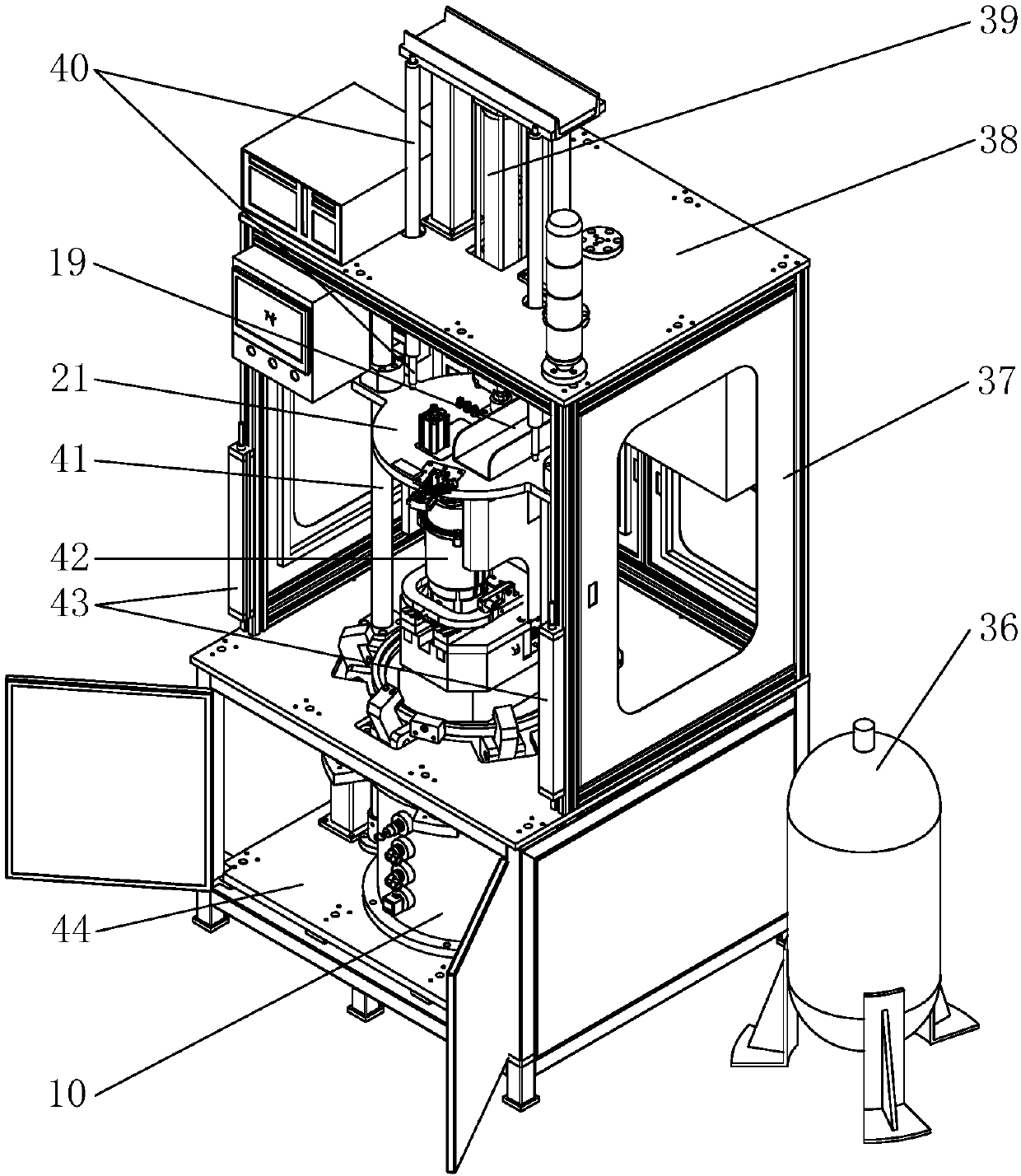
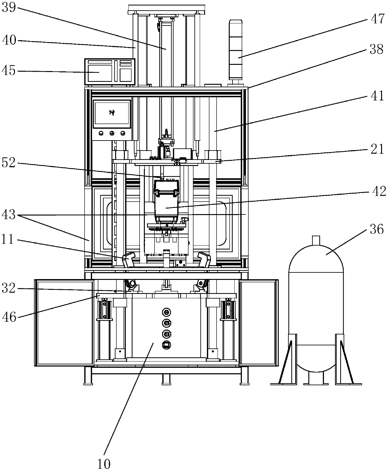
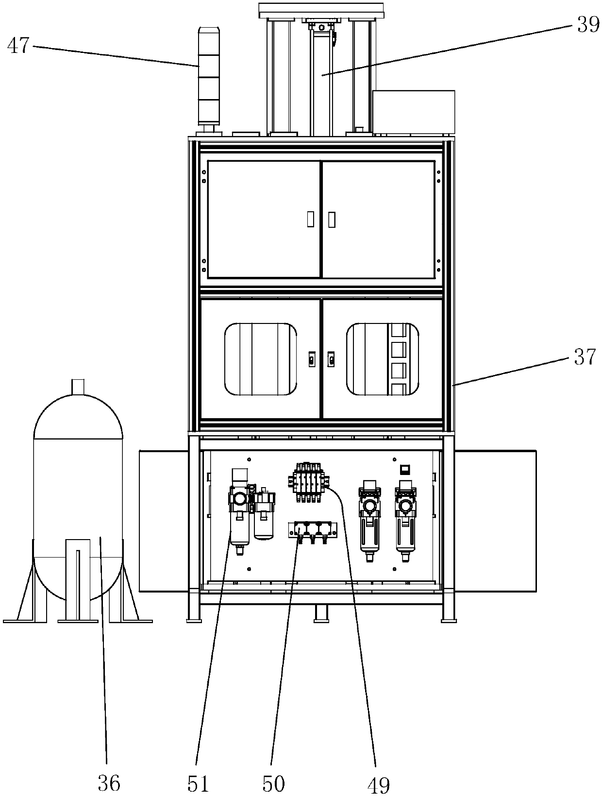
[0038] The leak detection equipment of the submersible pump, including the tank body 10 of the pressure tank fixed on the base 44 of the tank body 37 and the tank body 37, the base 44 outside the tank body 10 is evenly distributed with three or more vertical guide rods 41 in the circumferential direction , the top of the guide rod 41 is fixed on the top plate 38, and the tank cover 21 of the pressure tank is slid on the guide rod 41 between the top plate 38 and the tank body 10 and driven by the cylinder 39 fixed on the top plate 38. Lifting, the tank body 10 and the tank cover 21 are locked by an automatic locking device, and the lower side of the fixed vertical mounting plate 17 on the bottom surface of the tank cover 21 is provided with a supporting plate 28, a submersible pump positioning fixture and a cylinder drivi...


PUM


Abstract

The invention belongs to the technical field of a detection device, and relates to a sealing property detection device for a submersible pump. A pressure tank body and a guide bar at the outside of the tank body are fixed on a pedestal of a box; a tank cover of the pressure tank is slidingly arranged on the guide bar which is arranged between a top board and the tank body, and can be lifted and dropped driven by a cylinder; the tank body and the tank cover are locked together through an automatic locking device; the lower side of a vertical mounting board fixed on the bottom surface of the tank cover is provided with a supporting plate, a submersible pump positioning clamp and a bulkhead; the bulkhead is driven by the cylinder to move in the lateral direction and is used for blocking an oil chamber detection joint of the submersible pump; the middle part of the tank cover is provided with a bulkhead which is driven by the cylinder to move up and down and is used for blocking a motor chamber detection joint for the submersible pump; and the side wall of the tank cover is provided with a cable slot and a cable sealing locking block. The sealing property detection device for a submersible pump has the advantages of being accurate in the control motion, being high in detection precision, having more detection items, and being suitable for high accuracy detection of the submersible pump.

Description

technical field [0001] The invention belongs to the technical field of detection equipment, in particular to a sealing performance detection equipment of a submersible pump. Background technique [0002] As the name suggests, a submersible pump is a water pump that submerges into the water when it is working. It has very strict requirements on the airtightness of the water pump. At present, there are three common detection methods: one is the water bath method, the other is the differential pressure detection method, and the third is the rare gas detection method. three kinds. [0003] The detection method of the water bath method is to fill the inside of the water pump with a certain pressure of gas, sink the water pump into the water, and observe whether there is bubble phenomenon on the surface of the water pump through the eyes of the operator, so as to judge the tightness of the water pump; this detection method has the following points Serious deficiencies; first, the...

Claims


Application Information

Patent Timeline
Patent Type & Authority Patents(China)
IPC IPC(8): G01M3/26F04B51/00
CPCF04B51/00G01M3/26
Inventor 毛益波潘巍巍
Owner 新界泵业(浙江)有限公司
Learn More