Locking and separating structure for front face plate of drawer

A front panel and lock-away technology, applied in drawers, applications, home appliances, etc., can solve the problems of inconvenient daily use of drawer panels, inconvenient use by users, and unsatisfactory users, and reduce assembly steps. And the effect of manufacturing tolerance, quick disassembly and assembly, great flexibility

Active Publication Date: 2014-11-26
伍志勇
View PDF9 Cites 7 Cited by
  • Summary
  • Abstract
  • Description
  • Claims
  • Application Information

AI Technical Summary

Problems solved by technology

When the height of the panel of the drawer in this structure is relatively high, it is extremely easy to shake, which makes the user unsatisfied; and the connecting piece on the panel needs to be connected with the adjustment seat at the same time to fix the panel, which makes it inconvenient for the user to use, and the assembly after assembly The adjustment method of the drawer panel is not convenient for the daily use of the user

Method used


Image

  • Locking and separating structure for front face plate of drawer
  • Locking and separating structure for front face plate of drawer
  • Locking and separating structure for front face plate of drawer

Examples


no. 1 example

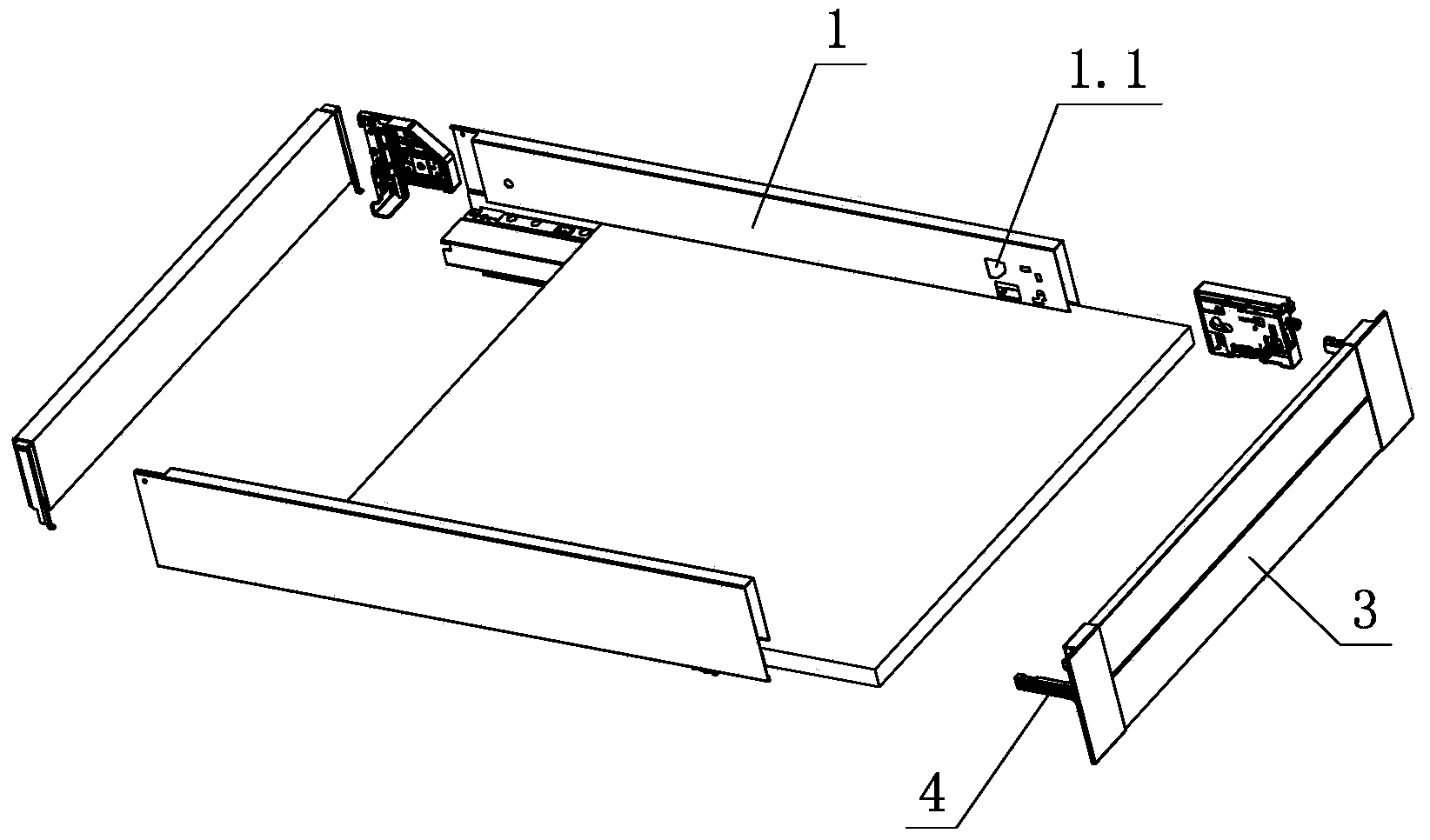
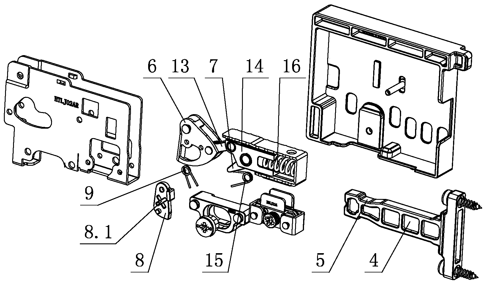
[0027] see Figure 1-Figure 8, which is used for the lock-off structure of the front panel of the drawer, including a fixing device arranged on the side panel 1, the front panel 3 is connected with the fixing device through a connecting element 4, and a set of locking and separating connections is provided on the fixing device The lock-off device of the element 4, the lock-off device includes a separation element 6, a finger-shaped element 7 and a holding element 8; wherein, when the connecting element 4 is installed, it is interlocked with the finger-shaped element 7 with force to realize automatic locking; When the connecting element 4 is disassembled, the tool 11 acts on the retaining element 8 with force, and drives the retaining element 8 to move, and then acts on the separating element 6 through the tool 11, and / or acts on the separating element 6 through the retaining element 8, finger-shaped The element 7 is separated from each other by the separation element 6 and the...

no. 2 example

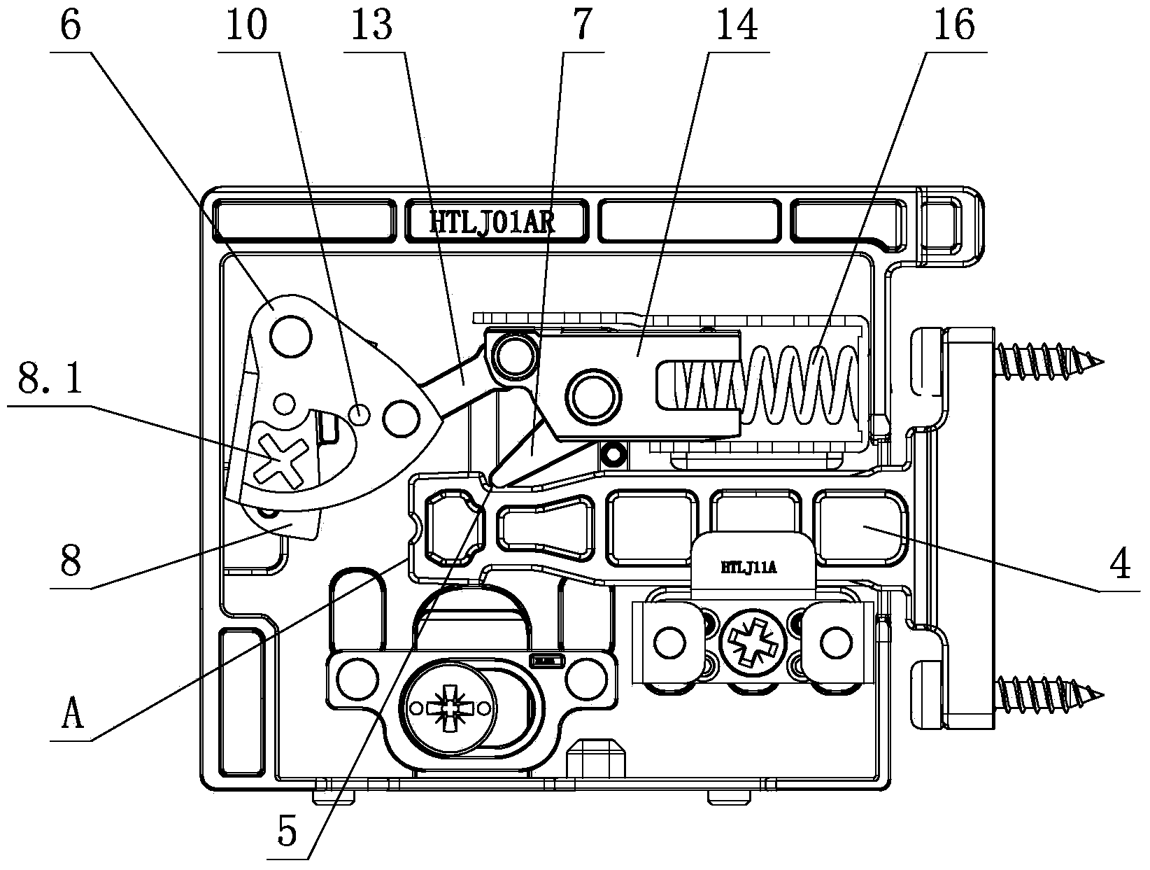
[0043] see Figure 9 , which is used for the lock-off structure of the front panel of the drawer, the separation element 6 is arranged on the fixing device through the swing of the pin shaft, and the holding element 8 is arranged on the separation element 6 through the swing of the pin shaft; the second elastic member 9 is a spring, and the spring is preferably It is a torsion spring, and one end acts on the holding element 8, and the other end acts on the separation element 6; the holding element 8 is driven to swing from the initial position by the tool 11 acting on the holding action part 8.1, and then acts on the separation element 6, And drive the separation element 6 to swing, the finger element 7 is engaged with and / or disengaged from the locking part 5 of the connection element 4 through the swing of the separation element 6, so as to realize the locking and / or separation of the locking device and the connection element 4.

[0044] Others are not described with the fir...

no. 3 example

[0046] see Figure 10 , Figure 11 , which is used for the lock-off structure of the front panel of the drawer. The separation element 6 is oscillated on the fixing device through a pin shaft, and the holding element 8 is a cam, which is rotated and positioned on the separation element 6; the second elastic member 9 is a spring, and the spring It is preferably a torsion spring, and one end acts on the holding element 8, and the other end acts on the separation element 6; the tool 11 acts on the holding part 8.1 and drives the holding element 8 to rotate from the initial position, and the holding element 8 rotates during the rotation process. , the transmission part 10 acts on the separation element 6, and drives the separation element 6 to swing, and the finger element 7 engages and / or disengages with the locking part 5 of the connection element 4 through the swing of the separation element 6, realizing the lock-out device and the connection Locking and / or disengagement of el...


PUM


Abstract

A locking and separating structure for a front face plate of a drawer comprises a fixing device arranged on a side plate. The front face plate is connected with the fixing device through one or more connecting elements. The fixing device is provided with one or more locking and separating devices used for locking and separating the connecting elements. Each locking and separating device comprises a separating element, a finger-shaped element and a holding element. When installed, the connecting elements are automatically locked in the mode that the connecting elements and the finger-shaped elements with acting force are fastened; when the connecting elements are detached, a tool acts on the holding elements with acting force and drives the holding elements to move, the tool and / or the holding elements act on the separating elements, the finger-shaped elements are separated from the connecting elements through the separating elements, and separation is achieved; when the connecting elements are separated from the finger-shaped elements, the positions of the connecting elements basically remain unchanged; the holding elements begin to return to initial positions at least when the tool is separated from the separating elements and / or the holding elements and the connecting elements are separated from the locking and separating devices with certain distances.

Description

technical field [0001] The invention relates to a drawer front panel, in particular to a lock-off structure for the drawer front panel. Background technique [0002] Chinese Patent Document No. CN 101224065A disclosed a panel locking and adjusting device for a drawer with slide rails on July 23, 2008. There is a guide groove in the adjustment seat for the sliding of the connecting piece, and a panel locking mechanism is arranged in the guide groove. The panel locking mechanism includes an eccentric cam arranged on the adjustment seat, the other end of which is hinged with the guide block through a connecting rod, and the swing rod One end is hinged on the guide block through the pin shaft, the torsion spring is sleeved on the pin shaft, one end is connected to the swing rod, the other end is connected to the guide block or the adjustment seat, the guide block is slidingly sleeved in the adjustment seat, and connected The end of the piece is connected to the other end of the...

Claims


Application Information

Patent Timeline
Patent Type & Authority Applications(China)
IPC IPC(8): A47B88/00A47B88/04
Inventor 伍志勇
Owner 伍志勇
Why Eureka
Try Eureka