Energy-saving and environment-friendly smelting furnace

An energy-saving, environmentally friendly, melting furnace technology, applied in furnaces, furnace components, stirring devices, etc.

Pending Publication Date: 2020-10-27
张广健
View PDF6 Cites 6 Cited by
  • Summary
  • Abstract
  • Description
  • Claims
  • Application Information

AI Technical Summary

Problems solved by technology

The disadvantage of this invention is that there is no mechanical lock between the upper cover and the stirring power source, so as to ensure that the lower stirring mechanism stops when feeding and taking out materials, and ensures the safety of personnel.

Method used


Image

  • Energy-saving and environment-friendly smelting furnace
  • Energy-saving and environment-friendly smelting furnace
  • Energy-saving and environment-friendly smelting furnace

Examples


specific Embodiment approach 1

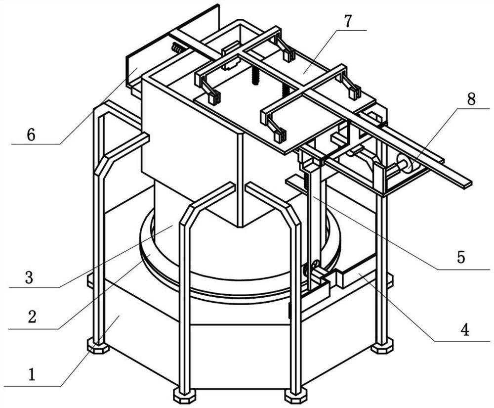
[0032] Combine below Figure 1-9 Describe this embodiment, an energy-saving and environment-friendly smelting furnace, including a supporting heating assembly 1, a material rotating and raising assembly 2, a stirring assembly 3, a driving assembly 4, an opening and closing assembly 5, a feeding assembly 6, a capping assembly 7 and a starting assembly 8 , the material rotating rising assembly 2 is rotatably connected to the supporting heating assembly 1, the stirring assembly 3 is fixedly connected to the material rotating rising assembly 2, the driving assembly 4 is fixedly connected to the right side of the supporting heating assembly 1, and the driving assembly 4 and the material rotating The lifting component 2 engages the transmission, the opening and closing component 5 is fixedly connected to the right side of the supporting heating component 1, the feeding component 6 is slidably connected to the left end of the upper part of the supporting heating component 1, and the c...

specific Embodiment approach 2

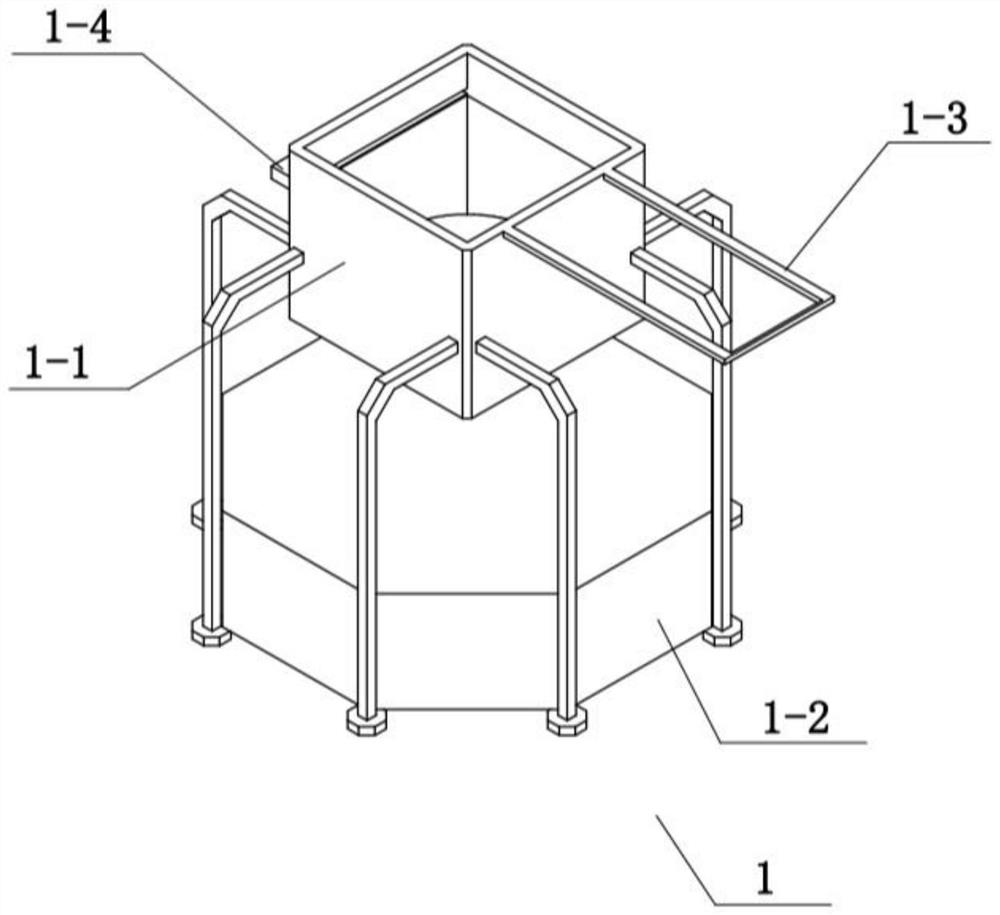
[0035] Combine below Figure 1-9 To illustrate this embodiment, the support heating assembly 1 includes an upper material box 1-1, a heater 1-2, a sliding rod 1-3 and a sliding frame 1-4, and the heater 1-2 is fixedly connected to the upper material box 1-2. 1, the sliding rod 1-3 is fixedly connected to the right side of the upper material box 1-1, and the sliding frame 1-4 is fixedly connected to the left side of the upper material box 1-1.

specific Embodiment approach 3

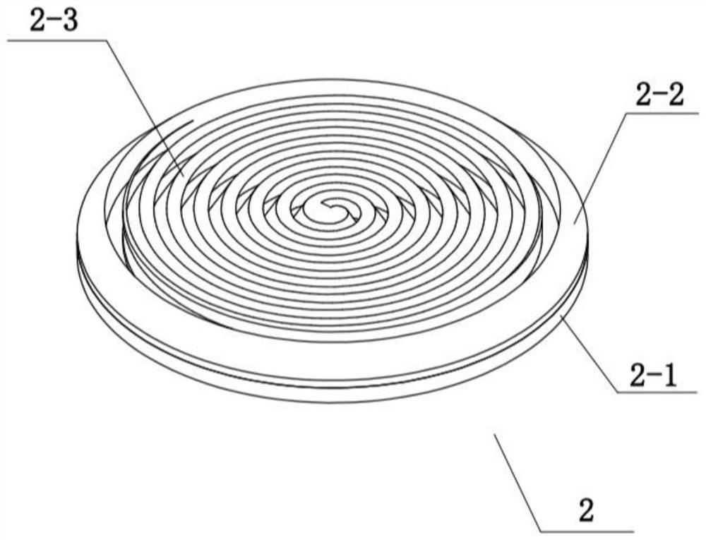
[0037]Combine below Figure 1-9 To illustrate this embodiment, the material rotating and rising assembly 2 includes a rotating disk 2-1, a rotating bevel tooth 2-2 and an inclined turbine plate 2-3, the rotating disk 2-1 is rotatably connected to the heater 1-2, and the rotating cone The teeth 2-2 are fixedly connected on the rotating disc 2-1, and the inclined turbine plate 2-3 is fixedly connected on the rotating disc 2-1.

[0038] The driving assembly 4 meshes to drive the rotating bevel gear 2-2 to rotate, and the rotating bevel gear 2-2 drives the rotating disc 2-1 to rotate, and the rotating disc 2-1 drives the inclined turbine plate 2-3 to rotate, and the inclined turbine plate 2-3 has a turbine shape It will make the melted material rotate and move centrifugally along the turbine groove, and the inclination angle of the turbine plate 2-3 will give the melted material an upward force, so that the melted material can be mixed up and down, which is more conducive to the r...


PUM


Abstract

The invention relates to the technical field of smelting furnaces, in particular to an energy-saving and environment-friendly smelting furnace. The energy-saving and environment-friendly smelting furnace comprises a supporting and heating component, a material rotating and lifting component, a stirring component, a driving component, an opening and closing component, a feeding component, a cover sealing component and a starting component, wherein the starting component is meshed to drive the cover sealing component to move to seal and close a feeding box in order to realize smelting and opening for material taking; the cover sealing component pushes the feeding component to realize safe feeding, and the personnel security is guaranteed; the driving component drives the material rotating and lifting component to rotate in order to achieve spiral up-down mixed stirring of the material bottom layer; the material rotating and lifting component drives the stirring component to rotate, so that the material stirring is achieved to accelerate the smelting speed; the cover sealing component pushes the opening and closing component to slide, so that the opening and closing component locks and opens the power output of the driving component, the automatic locking of the material rotating and lifting component and the stirring component during material feeding and material taking of the smelting furnace is realized, and the personal safety of operators is ensured.

Description

technical field [0001] The invention relates to the technical field of melting furnaces, in particular to an energy-saving and environment-friendly melting furnace. Background technique [0002] The invention with the publication number of CN111351354A discloses an energy-saving and environment-friendly melting furnace with uniform heating, which specifically relates to the technical field of boilers, including a melting furnace chamber. Material port, the top of the melting furnace cavity is provided with a crushing box, the crushing box is connected with the melting furnace cavity through the feeding port, the top of the crushing box is provided with a hopper, the hopper is connected with the crushing box, and the crushing box is connected with the melting furnace cavity. Two crushing rollers and two baffles that are axisymmetric to the vertical central axis of the hopper are arranged inside the box. The present invention crushes the material by using the crushing box wit...

Claims


Application Information

Patent Timeline
Patent Type & Authority Applications(China)
IPC IPC(8): F27D3/04F27D3/14F27D27/00
CPCF27D3/04F27D3/14F27D27/00
Inventor 张广健
Owner 张广健
Why Eureka
Try Eureka