Fixing device

A technology of fixing film and reflector, which is applied in electrography, optics, instruments, etc., can solve problems such as unfavorable displacement of reflector, and achieve the effects of improving heating efficiency, reducing start-up time, and suppressing heat loss.

Active Publication Date: 2011-05-11
BROTHER KOGYO KK
View PDF6 Cites 7 Cited by
  • Summary
  • Abstract
  • Description
  • Claims
  • Application Information

AI Technical Summary

Problems solved by technology

However, according to this configuration, the position of the reflecting plate relative to the clamping plate may be disadvantageously shifted from the correct position

Method used


Image

  • Fixing device
  • Fixing device
  • Fixing device

Examples


Embodiment Construction

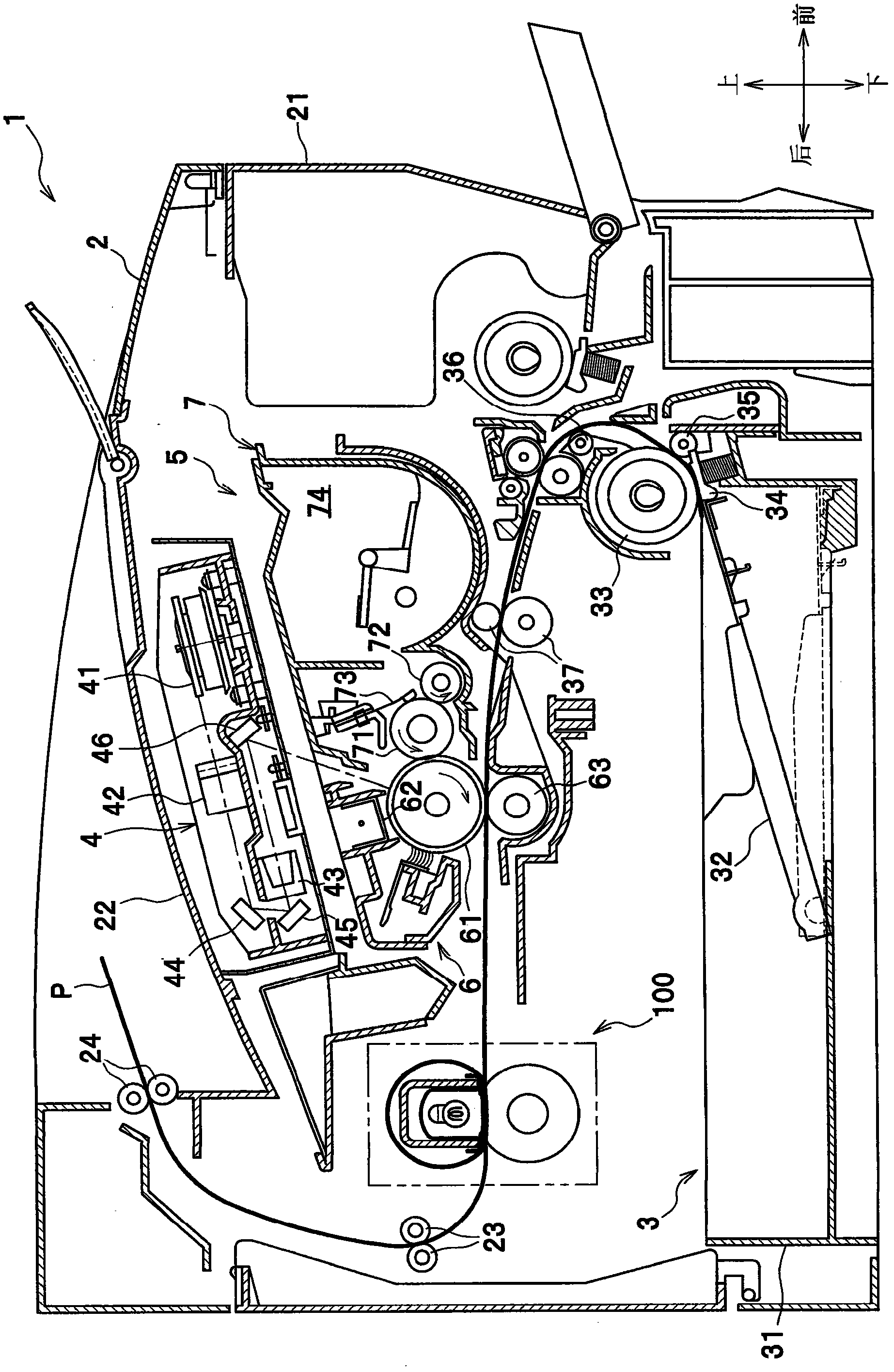
[0021] A detailed description will be given of exemplary embodiments of the present invention with reference to the accompanying drawings. In the following description, an overall arrangement of a laser printer 1 (image forming apparatus) provided with a fixing device 100 according to an embodiment of the present invention will be described, and then features of the fixing device 100 will be described in detail.

[0022]

[0023] as in figure 1 As shown in , a laser printer 1 includes a main body casing 2 and several members accommodated in the main body casing 2, the several members mainly including a sheet for feeding a sheet P (for example, of paper) as an example of a recording sheet. A material feeder unit 3, an exposure device 4, a process cartridge 5 for transferring a toner image (developer image) onto a sheet P, and a process cartridge 5 for thermally fixing the toner image transferred onto the sheet P The fixing device 100.

[0024] Hereinafter, in describing the...


PUM


Abstract

A fixing device for thermally fixing a developer image transferred onto a recording sheet, includes: a flexible fusing member which is flexibly deformable; a heating element; a nip member disposed in such a manner as to contact with a surface of the flexible fusing member and to allow the flexible fusing member to slide along the nip member; a reflecting plate configured to reflect radiant heat from the heating element in a direction toward the nip member; a backup member configured to nip the flexible fusing member with the nip member to thereby form a nip portion for the recording sheet between the flexible fusing member and the backup member; and a stay configured to support both end portions of the nip member. The reflecting plate has at least one flange portion, and the flange portion is held and supported between the nip member and the stay.

Description

technical field [0001] The present invention relates to a fixing device for thermally fixing a developer image transferred onto a recording sheet. Background technique [0002] A fixing device for use in an electrophotographic image forming apparatus is known in the art, for example, by JP2008-233886A. The fixing device includes a fixing film, a heater, a nip as a heating plate for forming a nip portion between the pressure roller and the nip through the fixing film, a reflection plate for reflecting radiant heat from the heater toward the nip, and a nip for Holder for heaters, splints, and reflectors. [0003] According to the fixing device, if the thickness of the nip is reduced, radiant heat emitted from the heater can be efficiently transferred to the fixing film. However, reducing the thickness of the splint may result in a decrease in the stiffness of the splint. [0004] Furthermore, in this conventional fixing device, the reflective plate is held in a cylindrical ...

Claims


Application Information

Patent Timeline
Patent Type & Authority Applications(China)
IPC IPC(8): G03G15/20
CPCG03G15/2053G03G15/2007
Inventor 宫内义弘藤原靖史松野卓士石田圭铃木登近藤知广
Owner BROTHER KOGYO KK
Why Eureka
Try Eureka