

UVB based multi-channel radar life detection instrument
A life detector and radar-type technology, applied in the field of non-contact life parameter detection, can solve the unsolved problems of multiple stationary human target recognition and two-dimensional positioning
- Summary
- Abstract
- Description
- Claims
- Application Information
AI Technical Summary
Problems solved by technology
Method used
Image

Examples
Embodiment 1
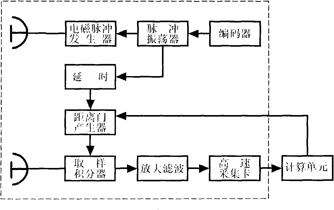
[0041] In this embodiment, a certain channel in the multi-channel is taken as an example for illustration. figure 1 It is a schematic block diagram of a single-channel ultra-wide-spectrum radar life detector system. First, the pulse oscillator generates a pulse signal, which triggers the electromagnetic pulse generator to generate a narrow pulse, which is radiated through the transmitting antenna. The reflected signal is sent to the sampling integrator through the receiving antenna, and the signal generated by the pulse oscillator passes through the delay circuit to generate a range gate to select the received signal. The signal passes through the sampling integration circuit, and after thousands of pulses are accumulated, the weak signal It is detected, amplified and filtered, and then sent to the computing unit after being sampled by a high-speed acquisition card. The computing unit analyzes, processes and recognizes the collected signal, and finally calculates the target di...
Embodiment 2
[0050] In this embodiment, one channel in the multi-channel is taken as an example to illustrate the weak signal enhancement method of a static target.
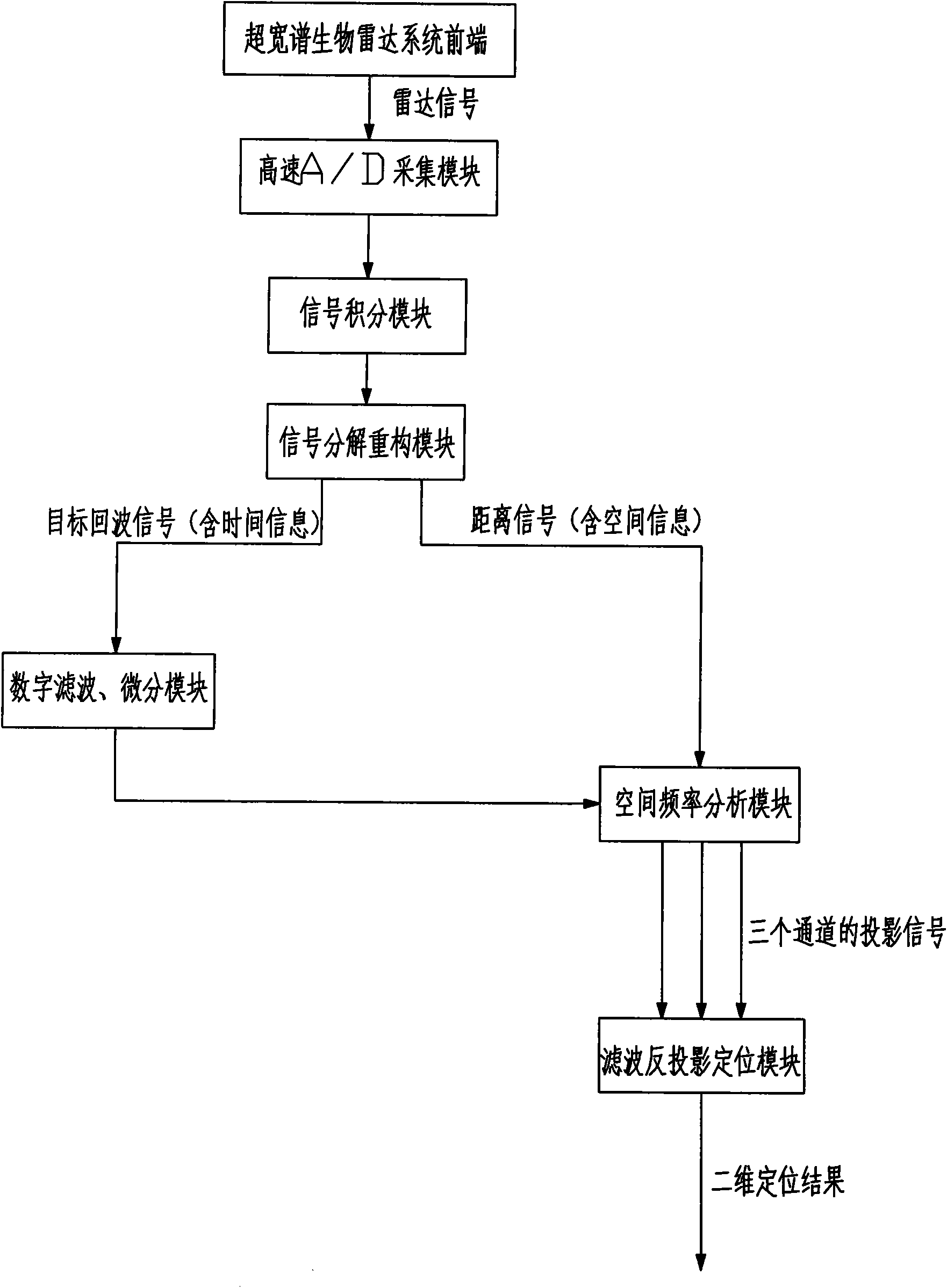
[0051] To realize the recognition of stationary human targets, the weak life signals of stationary human bodies should be enhanced first. In this embodiment, according to the characteristics of the UWB radar echo signal, the weak biomedical signal processing method is used to process the signal after high-speed sampling and enhance the useful signal to improve the signal-to-noise ratio and realize the basic recognition of human targets .
[0052] Use 8-point 4-point integration method to integrate the signal in the distance; then break up the signal for decomposition and reconstruction, and synthesize the target echo signal and distance signal; digitally filter and digitally differentiate the target echo signal to achieve Enhancement of weak useful signals.
[0053] 2.1 Integration of signals
[0054] The sampling rate of ...
Embodiment 3
[0091] In this embodiment, a certain channel in the multi-channel is taken as an example to illustrate the one-dimensional distance distinction method and the spatial frequency analysis method:
[0092] After the weak signal enhancement of the static target is completed, it is necessary to distinguish the distance of the human target. Because the range signal is an ultra-low frequency signal that reflects the distance information of the target, the present embodiment constructs a joint distribution function of space and frequency, and adopts the joint analysis method of space frequency (reformed Time-frequency analysis) analyzes the distance signal, describes the energy density and intensity of the signal at different distances and frequencies, and then gives the distance information of each human target.
[0093] Time-frequency analysis shows the change of the signal spectrum on the time axis. When the time variable is changed into a distance variable, the time-frequency anal...
PUM
 Abstract
Description
Claims
Application Information