Liquid stopping control device of drop infusion apparatus
A technology of a control device and an infusion set, which is applied to hypodermic injection devices and other directions, can solve the problem of blocking the drip bucket by the stop liquid control device, and achieve the effects of reducing operation trouble, improving convenience and economic benefits.
- Summary
- Abstract
- Description
- Claims
- Application Information
AI Technical Summary
Problems solved by technology
Method used
Image

Examples
Embodiment 1
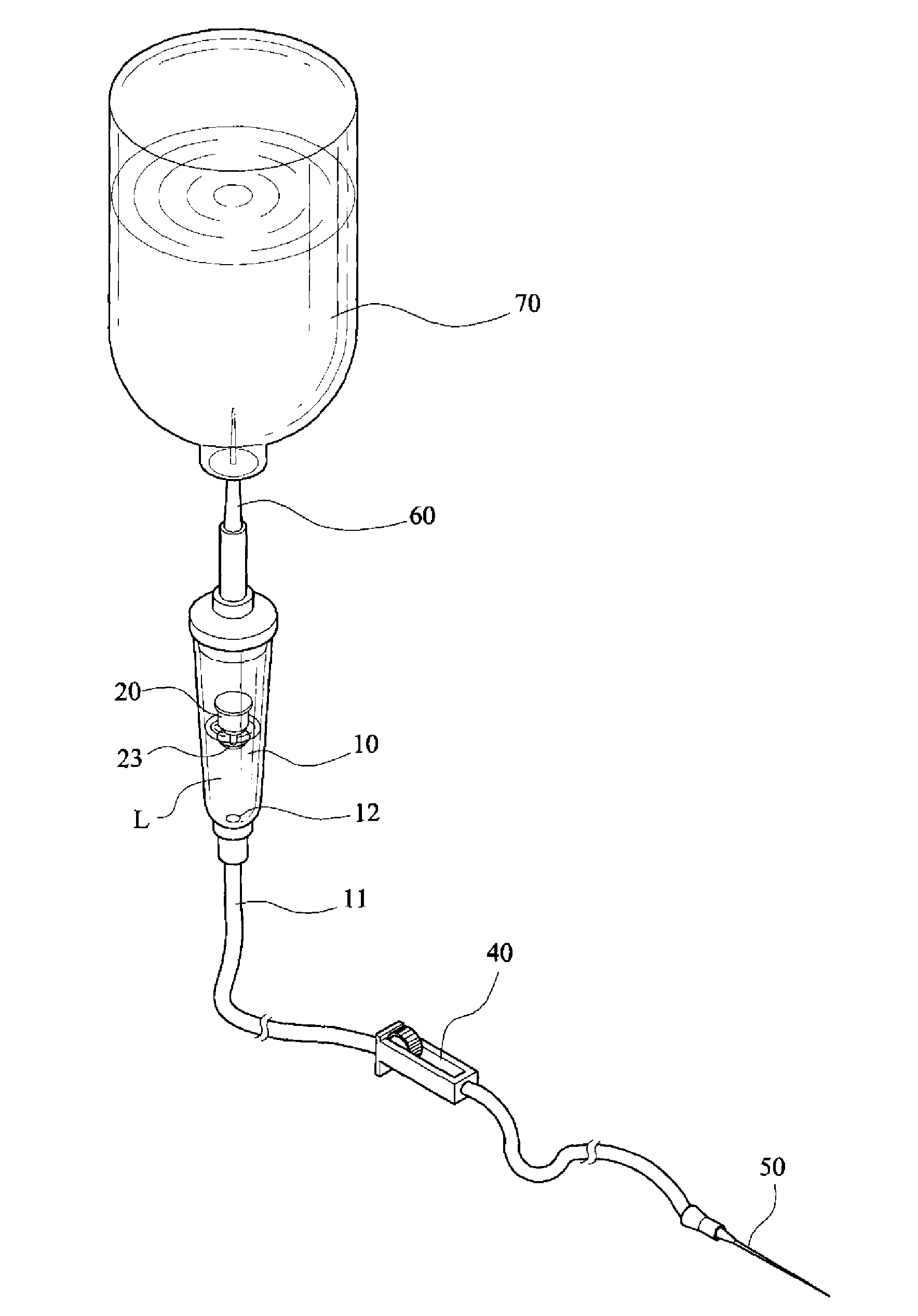
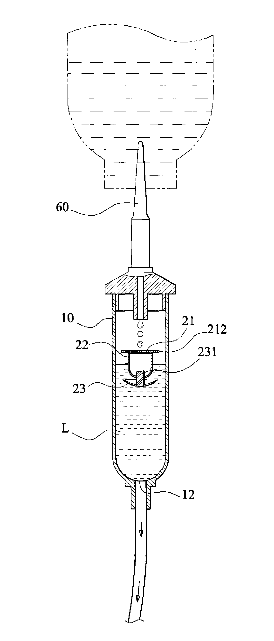
[0046] The overall structure of a specific embodiment of the present invention, with reference to the prior art figure 1 As shown, at least one liquid stop member 20 that can float in the dropping funnel 10 is included. The dropping funnel 10 also has a liquid inlet 13 for introducing the dripping liquid L, and a dripping liquid outlet 12 .
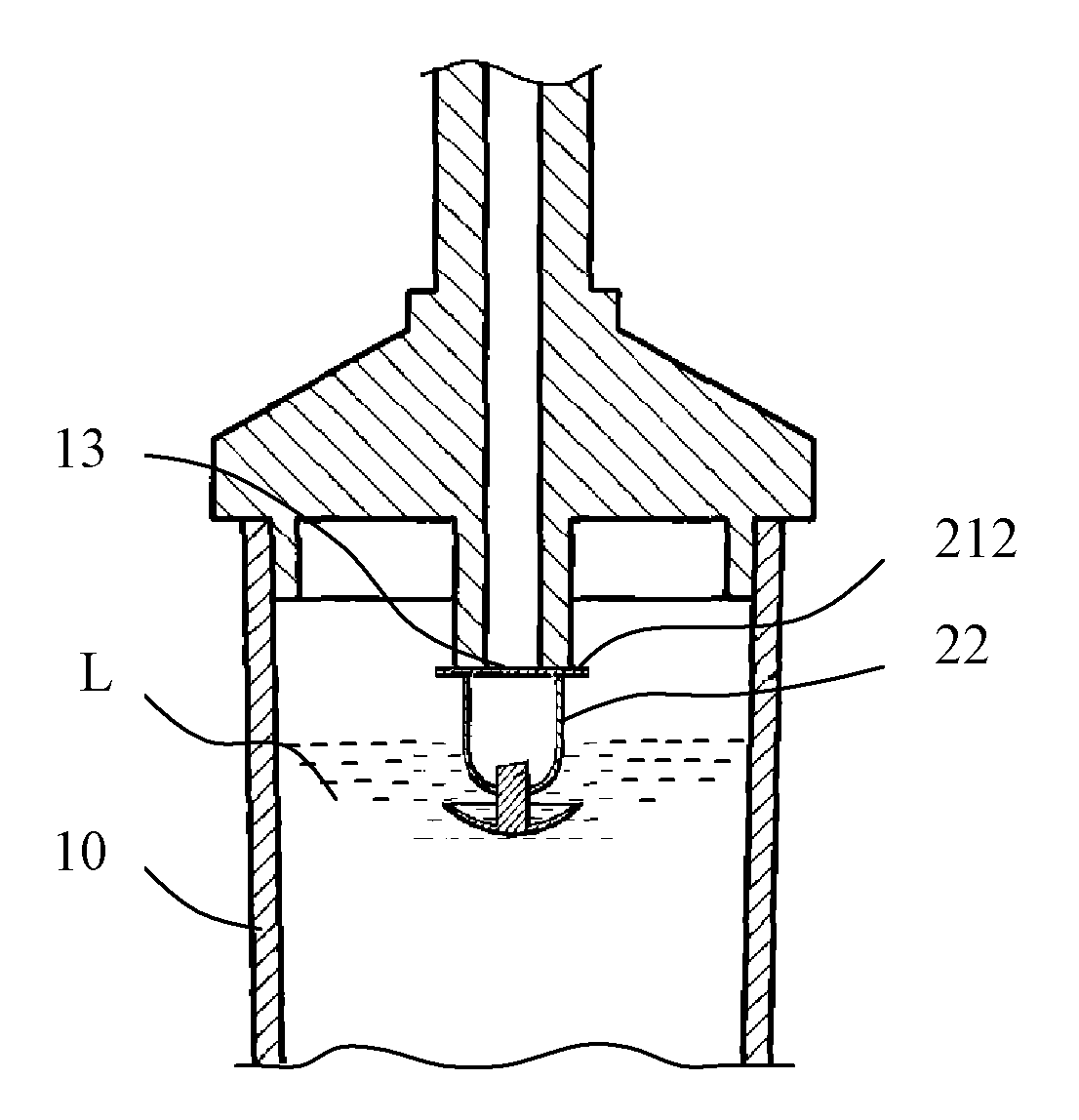
[0047] Such as Figure 4 , Figure 5 As shown, the liquid stop component 20 in this embodiment at least includes a hermetic floating body 22 and a spherical membrane unit 23 which are fixedly connected. The airtight floating body 22 is used to provide the buoyancy to make the liquid stop member 20 float up, and the spherical film unit 23 has the function of closing the droplet outlet 12 to stop the liquid.
[0048] In the present invention, an anti-clogging structure is also provided between the liquid stop member 20 and the liquid inlet portion 13 . In this embodiment, the anti-clogging structure is arranged between the top surface 2...
Embodiment 2
[0053] Such as Figure 10 , Figure 11 As shown, the structure of this embodiment is basically the same as that of Embodiment 1. The liquid-stopping component 20 at least includes an airtight floating body 22 and a spherical membrane unit 23 fixedly connected, and the anti-clogging structure is arranged on the top surface 212 of the airtight floating body 22 and Between the liquid inlet parts 13.
[0054] The difference is that the anti-clogging structure in this embodiment is a drainage groove 213 provided on the top surface 212 of the liquid-stop component 20 . The shape of the orthographic projection of the drainage groove 213 should be different from the cross-sectional shape of the liquid inlet part 13, so that at least one liquid channel can be formed between the two when the two are abutted against each other for dripping liquid to go down.
[0055] Specifically, when the cross section of the liquid inlet portion 13 is circular as shown in this embodiment, in differen...
Embodiment 3
[0059] The structure of this embodiment is basically the same as that of Embodiment 2, except that the anti-clogging structure in this embodiment is at least one through hole (not shown) opened on the top surface 212 of the liquid-stop component 20 .
[0060] The positions of the inlet end and the outlet end of the through hole need to be specially set. That is, the inlet end of the through hole must communicate with the liquid inlet 13, and the outlet end of the through hole must communicate with the cavity of the dropping funnel 10, and the through hole itself does not destroy the sealing of the airtight floating body 22.
[0061] In this way, with the help of the drainage channel formed between the liquid inlet part 13 and the inner cavity of the drip storage tube 10 by means of the through hole, the smooth downward flow of the drip can be realized.
PUM
 Abstract
Description
Claims
Application Information
 - R&D
- Intellectual Property
- Life Sciences
- Materials
- Tech Scout
- Unparalleled Data Quality
- Higher Quality Content
- 60% Fewer Hallucinations
Browse by: Latest US Patents, China's latest patents, Technical Efficacy Thesaurus, Application Domain, Technology Topic, Popular Technical Reports.
© 2025 PatSnap. All rights reserved.Legal|Privacy policy|Modern Slavery Act Transparency Statement|Sitemap|About US| Contact US: help@patsnap.com