LED lamp tube

An LED lamp tube and lamp cap technology, which is applied in the field of lighting, can solve the problems of small lighting range and poor heat dissipation effect, and achieve the effects of reducing heat dissipation burden, improving heat dissipation efficiency and improving lighting effect.

Inactive Publication Date: 2011-05-18
东莞宏灿光电制品有限公司
View PDF5 Cites 0 Cited by
  • Summary
  • Abstract
  • Description
  • Claims
  • Application Information

AI Technical Summary

Problems solved by technology

The problem with the current LED light tube is that the LED is placed inside the light tube, there is air between the LED and the light tube shell, the power supply is designed inside the light tube, and the heat dissipation effect is poor.
In addition, the LED bottom plate on which the LEDs are installed is located at the center of the LED light tube, which makes the light emitted by the LEDs only pass through the 180° light-transmitting cover, and the lighting range is too small

Method used


Image

  • LED lamp tube
  • LED lamp tube
  • LED lamp tube

Examples


Embodiment Construction

[0022] The present invention will be further described in conjunction with the following examples.

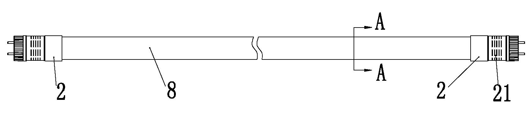
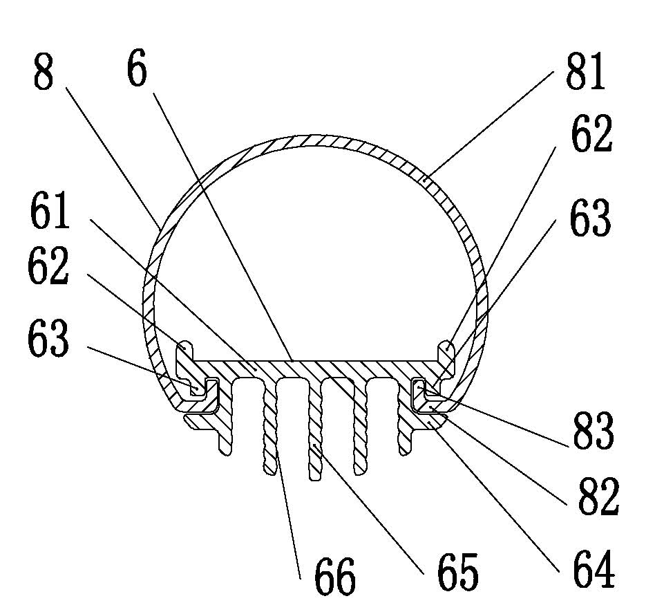
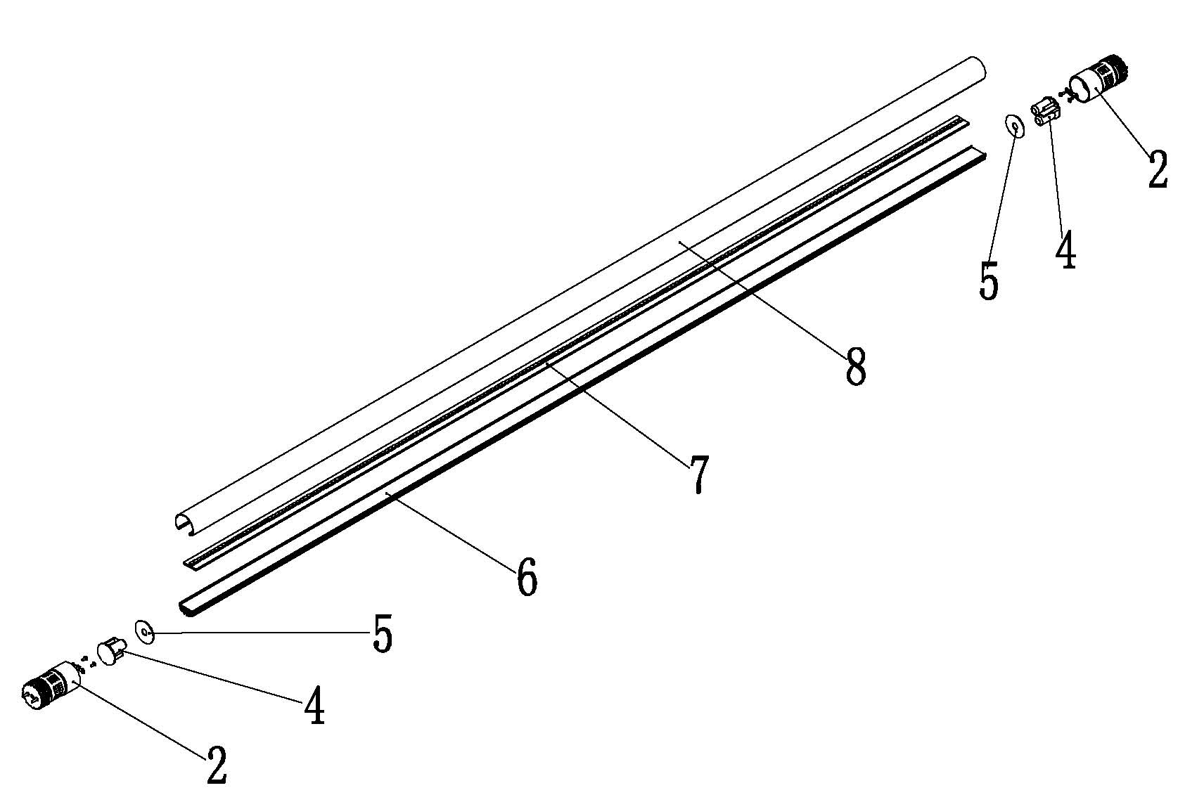
[0023] An example of the LED lamp tube of the present invention is Figure 1-Figure 3 As shown, it includes an upper cover 8, an LED base plate 7, a radiator 6, a power supply 4 and a lamp holder 2, the LED base plate 7 is installed between the upper cover 8 and the radiator 6, and the lamp holder 2 is installed on the LED The two ends of the lamp tube are characterized in that: the LED base plate 7 and the radiator 6 are closely mounted together, the cross section of the upper cover 8 is a circle greater than 180°, and the transverse section of the radiator 6 The section is a segment of a circle less than 180°, and the cross section of the upper cover 8 and the radiator 6 forms a complete circle.

[0024] The power supply 4 is installed in the lamp caps 2 at both ends of the LED lamp tube.

[0025] The lamp holder 2 is provided with heat dissipation seams 21 to enhance the h...


PUM


Abstract

The invention discloses an LED lamp tube comprising an upper cover, an LED base plate, a heat radiator, a power supply and a lamp cap; the LED base plate is installed between the upper cover and the heat radiator; the lamp cap is installed at two ends of the LED lamp tube; the LED base plate clings to the heat radiator and the LED base and the heat radiator are installed together; the cross section of the upper cover is a segment of more than 180 DEG; the cross section of the heat radiator is a segment of less than 180 DEG; and the cross sections of the upper cover and the heat radiator form an entire circle. In the LED lamp tube provided by the invention, the LED base plate is tightly connected with the heat radiator, and no air blockage exists between the LED base plate and the heat radiator, therefore, the heat radiation efficiency is greatly increased; the power supply is arranged at two ends of the LED lamp tube, thus, the heat of the power supply is prevented from entering the LED lamp tube, and the heat radiation load of the heat radiator is lowered, and the running reliability of the LED lamp tube is improved; and the transmitting angle of the upper cover exceeds 180 DEG, therefore, a better lighting effect is obtained.

Description

technical field [0001] The invention relates to the technical field of lighting, in particular to an LED lamp tube. Background technique [0002] At present, LED lights have become a trend in the field of lighting technology. But for the vast majority of families, fluorescent tubes are still used, so it is necessary to design the specifications of LED lamps to be installed on the lamp holders of ordinary fluorescent lamps, so as to avoid the waste caused by large-scale replacement of lamp holders . The existing problem of the LED lamp tube is that the LED is placed inside the lamp tube, there is air between the LED and the lamp tube shell, the power supply is designed inside the lamp tube, and the heat dissipation effect is poor. In addition, the LED bottom plate on which the LED is installed is located at the center of the LED light tube, which makes the light emitted by the LED only pass through the 180° light-transmitting cover, and the lighting range is too small. Co...

Claims


Application Information

Patent Timeline
Patent Type & Authority Applications(China)
IPC IPC(8): F21S2/00F21V29/00F21V17/10F21Y101/02F21V29/76F21V29/83
Inventor 刘昆兵赖显洋张俊许韩锋唐伟佳
Owner 东莞宏灿光电制品有限公司
Why Eureka
Try Eureka