Check patentability & draft patents in minutes with Patsnap Eureka AI!

Radio frequency band-pass filter circuit

A technology of filtering circuit and radio frequency band, which is applied in the field of filtering, can solve the problems of reducing the receiving sensitivity of wireless receiving equipment, poor receiving immunity of wireless receiving equipment, and the inability to effectively suppress stray signals, etc., so as to ensure receiving sensitivity and receiving anti-interference performance, improve reception immunity, and achieve the effect of spurious suppression

Active Publication Date: 2011-05-18
HYTERA COMM CORP
View PDF3 Cites 2 Cited by
  • Summary
  • Abstract
  • Description
  • Claims
  • Application Information

AI Technical Summary

Problems solved by technology

[0004] However, in this RF bandpass filter circuit, because of the strong capacitive coupling form between stages, the bandwidth will become larger as the frequency rises, and this circuit has only one zero point, and the zero point is on the left side of the waveform, so it cannot Ensure that the spurious signals on the right side of the near end of the radio frequency signal are effectively suppressed, and the filtering effect is poor, resulting in poor reception immunity of the wireless receiving device; and if you want to suppress spurious signals, improve the receiving immunity of the wireless receiving device interference, it is necessary to reduce the bandwidth of the RF bandpass filter circuit, which will increase the loss of the filter circuit and reduce the receiving sensitivity of the wireless receiving device

Method used


Image

  • Radio frequency band-pass filter circuit
  • Radio frequency band-pass filter circuit
  • Radio frequency band-pass filter circuit

Examples


Embodiment Construction

[0036] Hereinafter, the realization of the radio frequency band-pass filter circuit of the embodiment of the present invention will be described in detail in conjunction with the accompanying drawings.

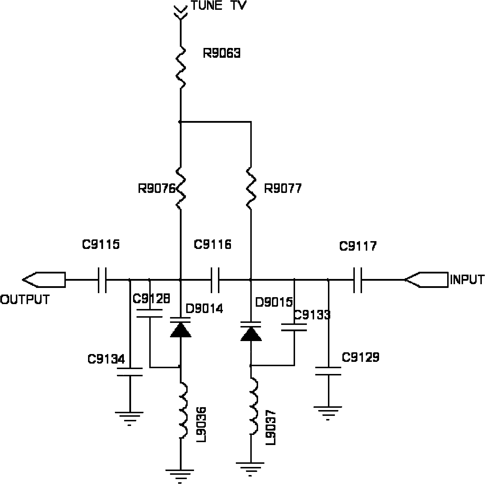
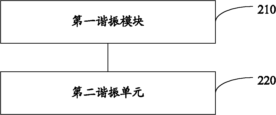
[0037] figure 2 It is a schematic structural diagram of a radio frequency bandpass filter circuit according to an embodiment of the present invention, as figure 2 As shown, the circuit includes:

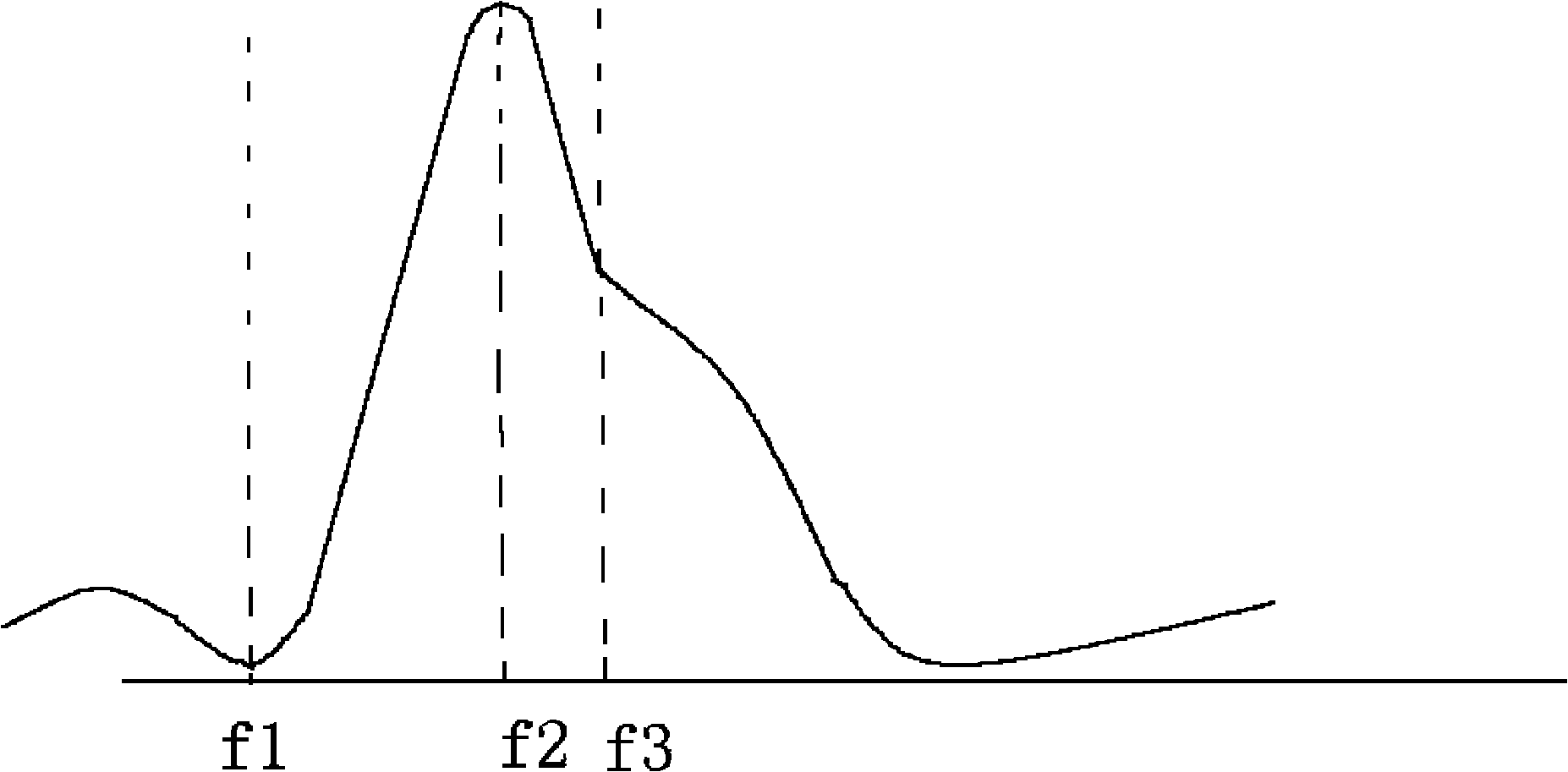
[0038] The first resonant module 210 is used to receive radio frequency signals, suppress the radio frequency signals of the preset first resonant frequency in the radio frequency signals; Other radio frequency signals other than the second resonant frequency are suppressed;

[0039] The second resonance unit 220 is configured to receive the radio frequency signal output by the first resonance module, and suppress the radio frequency signal of the preset third resonance frequency in the radio frequency signal.

[0040] Wherein, the first resonant frequency and the third resonant...


PUM


Abstract

The invention discloses a radio frequency band-pass filter circuit which comprises a first resonance module and a second resonance unit, wherein the first resonance module is used for receiving ratio frequency signals, suppressing ratio frequency signals with a first preset resonance frequency in the ratio frequency signals, carrying out frequency selection on ratio frequency signals with a second preset resonance frequency and suppressing other ratio frequency signals beyond the ratio frequency signals with the second preset resonance frequency; and the second resonance unit is used for receiving the ratio frequency signals output by the first resonance module and suppressing ratio frequency signals with a third preset resonance frequency in the radio frequency signals. The circuit has good filter effect and also can guarantee the receiving interference resistance and the receiving sensitivity of ratio receiving equipment.

Description

technical field [0001] The invention relates to filter technology, in particular to a radio frequency band-pass filter circuit. Background technique [0002] Receiving immunity and receiving sensitivity are very important for wireless receiving equipment such as receivers, and these requirements are directly related to the radio frequency bandpass filter of wireless receiving equipment. [0003] The existing radio frequency bandpass filter basically adopts the circuit structure of strong capacitive coupling or parallel connection of inductance and capacitance with fixed zero point coupling, as follows figure 1 In the shown RF bandpass filter circuit, the capacitance values ​​of the varactors D9014 and D9015 are tuned by the controller TUNE TV to obtain different resonant frequency points, thereby realizing the selectivity of different frequencies. [0004] However, in this RF bandpass filter circuit, because of the strong capacitive coupling form between stages, the bandwid...

Claims


Application Information

Patent Timeline
IPC IPC(8): H03H7/12
Inventor 罗海军范小方
Owner HYTERA COMM CORP
Features
  • R&D
  • Intellectual Property
  • Life Sciences
  • Materials
  • Tech Scout
  • Unparalleled Data Quality
  • Higher Quality Content
  • 60% Fewer Hallucinations
Learn More