Eureka AIR delivers breakthrough ideas for toughest innovation challenges, trusted by R&D personnel around the world.

Fixed Constant Velocity Universal Joint

A constant velocity universal joint, fixed technology, applied in the direction of elastic couplings, mechanical equipment, couplings, etc., can solve the problems of not having track grooves, and achieve the effects of size reduction, rigidity improvement, and edge load reduction

Active Publication Date: 2016-05-04
NTN CORP
View PDF11 Cites 0 Cited by
  • Summary
  • Abstract
  • Description
  • Claims
  • Application Information

AI Technical Summary

Problems solved by technology

In addition, in Patent Document 5, there are also six balls, and there is no linear portion of the track groove.

Method used


Image

  • Fixed Constant Velocity Universal Joint
  • Fixed Constant Velocity Universal Joint
  • Fixed Constant Velocity Universal Joint

Examples


Embodiment 1

[0095] A common angle (operating angle of 6°) durability test was carried out under relatively large torque conditions, and the results are shown in Surface 2 below. In this case, two samples of conventional products (conventional product No.1, conventional product No.2), and two samples of the above-mentioned product A1 of the present invention (product A1 of the present invention, product A1 of the present invention No. 2 ), the samples of the product A2 of the present invention and the product B of the present invention are respectively made four (product A2No.1 of the present invention, product A2No.2 of the present invention, product A2No.3 of the present invention, product A2No.4 of the present invention, product A2No.4 of the present invention Product B1No.1, Product B1No.2 of the present invention, Product B1No.3 of the present invention, Product B1No.4 of the present invention). The durability test was performed under the conditions of a torque of 834 Nm and a rotatio...

Embodiment 2

[0102] Next, a high-angle durability test was carried out, the results of which are shown in Table 3 below. In this case, two samples of the conventional product are made (conventional product No.1, conventional product No.2), and two samples of the product A1 of the present invention, product A2 of the present invention, and product B of the present invention are prepared respectively (product No. A1No.1, product of the present invention A1No.2, product of the present invention A2No.1, product of the present invention A2No.2, product of the present invention B1No.1, product of the present invention B1No.2). The durability test was carried out under the conditions of a torque of 549 Nm, an angle of 0 to 46° (swing), and a rotation speed of 80 r / min.

[0103] 〔table 3〕

[0104] [table 3]

[0105]

[0106] In the case of running time of 3.7 hours, conventional product No. 1 and conventional product No. 2 were on the inner side of the outer ring, and there was a defect due t...


PUM


Abstract

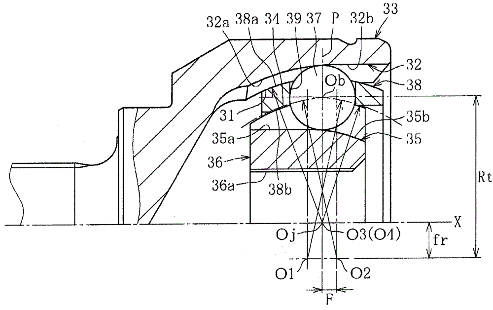
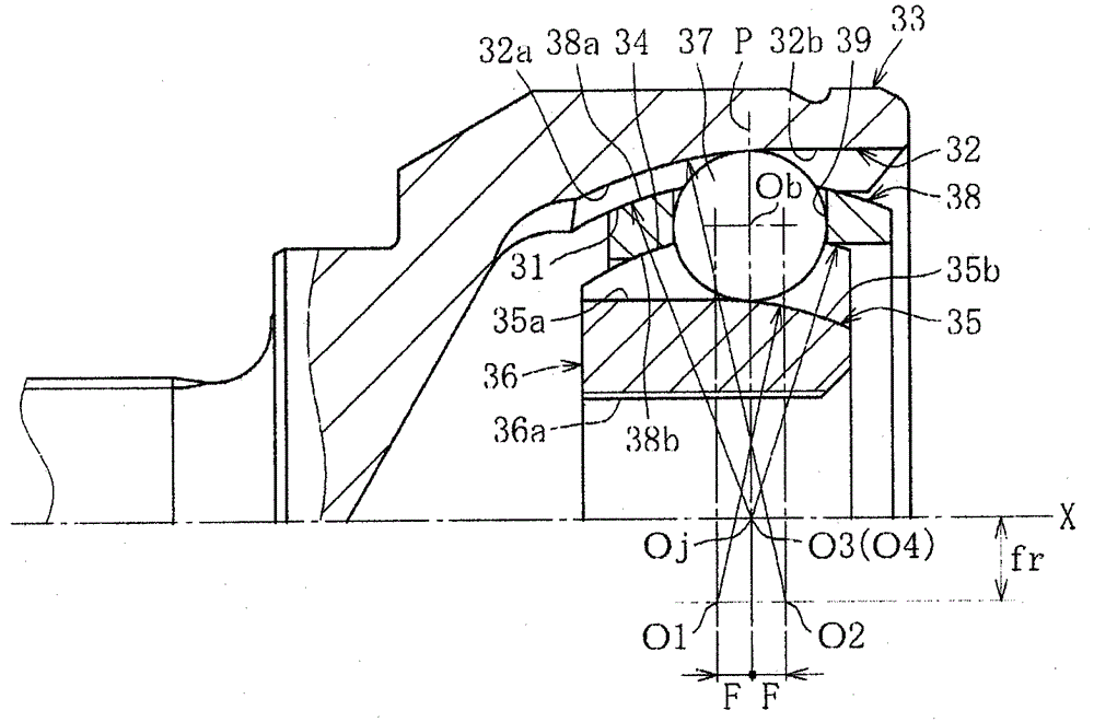
The present invention relates to an eight-ball non-undercut type fixed constant velocity universal joint capable of improving torque capacity at high operating angles while ensuring durability at low operating angles. In this eight-ball non-undercut type fixed constant velocity universal joint, the center of the track groove (32) of the outer joint member and the center of the track groove (32) of the inner joint member are separated from the joint center plane (P) respectively. They are separated on both sides in the axial direction, and are biased at positions separated from the center axis (X) of the joint to the opposite side in the radial direction with respect to these track grooves (32). The distance between the center of the track groove (32) of the outer joint part and the center of the ball (37) is Rt, and the axial distance between the center of the track groove (32) of the outer joint part and the center plane (P) of the joint When it is F, the ratio R1 of F to Rt is 0.061R1≤0.087, and when the distance between the center of the track groove (32) of the outer joint member and the central axis (X) of the joint, that is, the offset in the radial direction is fr, The ratio R3 of fr to Rt is 0.07≤R3≤0.19.

Description

technical field [0001] The present invention relates to a fixed constant velocity universal joint, in particular to a type that only allows angular displacement between two shafts on the driving side and the driven side connected together, used in motor vehicles or various industrial machinery An undercut type fixed constant velocity universal joint with eight torque transmission balls used in the power transmission system. Background technique [0002] Among the fixed type constant velocity universal joints, there are cage type (BJ) (for example, Patent Document 1), unundercut type (UJ), and the like. [0003] Ball cage type fixed constant velocity universal joints, such as Figure 13 As shown, the outer ring 3 as the outer joint part has a plurality of track grooves 2 formed at equal intervals in the circumferential direction on the inner spherical surface 1 along the axial direction, and the outer ring 3 is formed on the outer spherical surface 4 at equal intervals in the...

Claims


Application Information

Patent Timeline
Patent Type & Authority Patents(China)
IPC IPC(8): F16D3/2237F16D3/2245F16D3/20
CPCF16D3/2237F16D3/2245F16D2003/22309
Inventor 曾根启助大场浩量吉田和彦伊藤洁洋
Owner NTN CORP
Why Eureka
Eureka Blog
Learn More