A combined electrical measurement device

A technology for measuring devices and currents, applied in the direction of measuring devices, measuring electrical variables, measuring current/voltage, etc.

Active Publication Date: 2011-05-18
ABB (SCHWEIZ) AG
View PDF4 Cites 17 Cited by
  • Summary
  • Abstract
  • Description
  • Claims
  • Application Information

AI Technical Summary

Problems solved by technology

[0006] Even if existing schemes provide satisfactory results, there is still a need and room for further improvement

Method used


Image

  • A combined electrical measurement device
  • A combined electrical measurement device
  • A combined electrical measurement device

Examples


Embodiment Construction

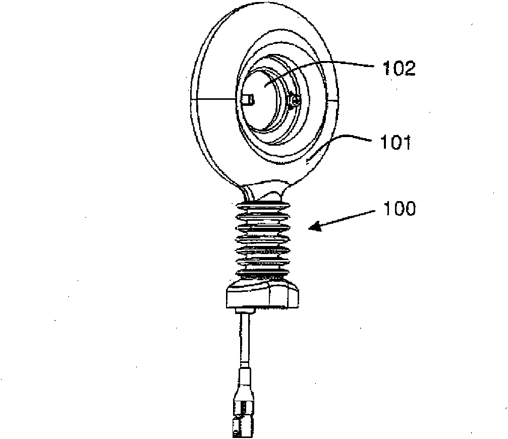
[0025] figure 1 A possible embodiment of a combined measuring device according to the invention, indicated generally by reference numeral 100, is shown. In the illustrated embodiment, the device 100 comprises a support 101 having a through opening 102 allowing the passage of a conductor (not shown) whose current and voltage are to be measured. For example, the support body 101 may be entirely made of a single insulating material or have a housing or housing made of several insulating materials and preferably fill the housing with different insulating materials. For example, commonly available thermosetting or thermoplastic materials may be used.

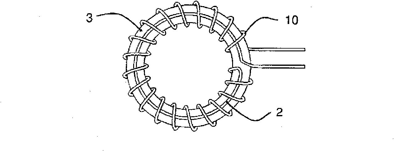
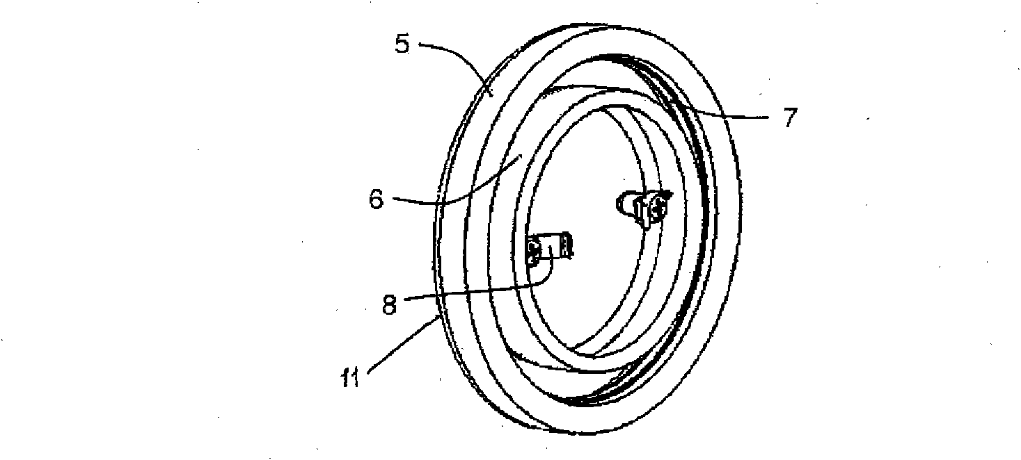
[0026] The measuring device 100 also comprises a current sensor 5 housed in the support 101 , a voltage sensor at least partially in the support 101 itself and a shield 11 placed around the current sensor 5 and connected to ground potential.

[0027] Advantageously, the current sensor 5 and the voltage sensor are mutually arranged ...


PUM


Abstract

A combined measurement device (100) for measuring current and/or voltage of an electrical conductor, comprises a supporting body (101), a current sensor (5) housed inside the supporting body (101) and a voltage sensor located at least partially inside the supporting body. A shielding (11) is positioned around the current sensor (5). The current sensor (5) and the voltage sensor are mutually arranged so as the shielding (11) shields at least partially both the current sensor (5) and the voltage sensor against external electric field disturbances.

Description

technical field [0001] The invention relates to a combined measuring device for measuring current and / or voltage of electrical conductors. Background technique [0002] In the field of electrical applications, the use of measuring devices for measuring current and / or voltage of electrical conductors is well known. Typical examples of such devices are represented by so-called instrument transformers, eg current or voltage transformers. [0003] As this is a common rule for many applications in many technical fields, these measuring devices are also required to operate in a very efficient way and according to a constructive solution that is as economically competitive, reliable and simplified as possible. perform their basic tasks. In practical application, some important requirements to be fulfilled by these devices are, for example, good electric field distribution, adequate safety, output signals with a sufficient level of accuracy, especially when the output signal from ...

Claims


Application Information

Patent Timeline
Patent Type & Authority Applications(China)
IPC IPC(8): G01R19/00
CPCG01R15/16G01R15/142G01R15/181Y10T29/49
Inventor 拉德克·亚沃拉彼得·J·克拉尔
Owner ABB (SCHWEIZ) AG
Why Eureka
Try Eureka