Space deployment mechanism driven based on multi-piezoelectric vibrator step crawling mode

A mode-driven, space-expanding technology, applied in generators/motors, piezoelectric effect/electrostrictive or magnetostrictive motors, electrical components, etc., can solve problems such as electromagnetic interference, complex structure, complex self-locking, etc. Achieve the effect of small weight, no electromagnetic interference, power-off self-locking energy consumption

Active Publication Date: 2015-10-07
HARBIN INST OF TECH
View PDF8 Cites 4 Cited by
  • Summary
  • Abstract
  • Description
  • Claims
  • Application Information

AI Technical Summary

Problems solved by technology

[0004] In order to solve the problems of complex structure, serious electromagnetic interference and complex self-locking existing in the existing electromagnetic motor-driven space expansion mechanism, the present invention proposes a space expansion mechanism driven by a multi-piezoelectric vibrator step-peristaltic mode

Method used


Image

  • Space deployment mechanism driven based on multi-piezoelectric vibrator step crawling mode
  • Space deployment mechanism driven based on multi-piezoelectric vibrator step crawling mode
  • Space deployment mechanism driven based on multi-piezoelectric vibrator step crawling mode

Examples


specific Embodiment approach 1

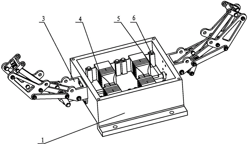
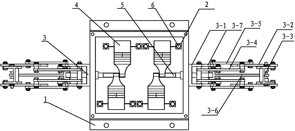
[0013] Specific implementation mode 1. Combination figure 1 and figure 2 Describe this specific embodiment. The space expansion mechanism driven by the multi-piezoelectric vibrator stepping and creeping mode described in this specific embodiment includes a base 1, two shaft sleeves, two expansion mechanisms 3, and four piezoelectric vibrators 4. , two drive shafts 5 and mounting base 2, through holes are opened at the center of the two opposite side walls of the base 1, and the through holes on the two side walls are coaxial, and the two shaft sleeves fixed in the two through holes, the two deployment mechanisms 3 are respectively fixed on the two opposite side walls of the base 1, the ends of the four piezoelectric vibrators 4 are all fixed inside the base 1 through the mounting base 2, and the four The head ends of the two piezoelectric vibrators 4 are located on the same straight line, one end of the two drive shafts 5 is closely connected with the two piezoelectric vibra...

specific Embodiment approach 2

[0016] Specific embodiment two, combine figure 1 and figure 2 This specific embodiment is described. The difference between this specific embodiment and the space expansion mechanism driven by the multi-piezoelectric vibrator stepping and creeping mode described in the first specific embodiment is that the mounting seat 2 and the base 1 are fixedly connected by bolts 6 .

specific Embodiment approach 3

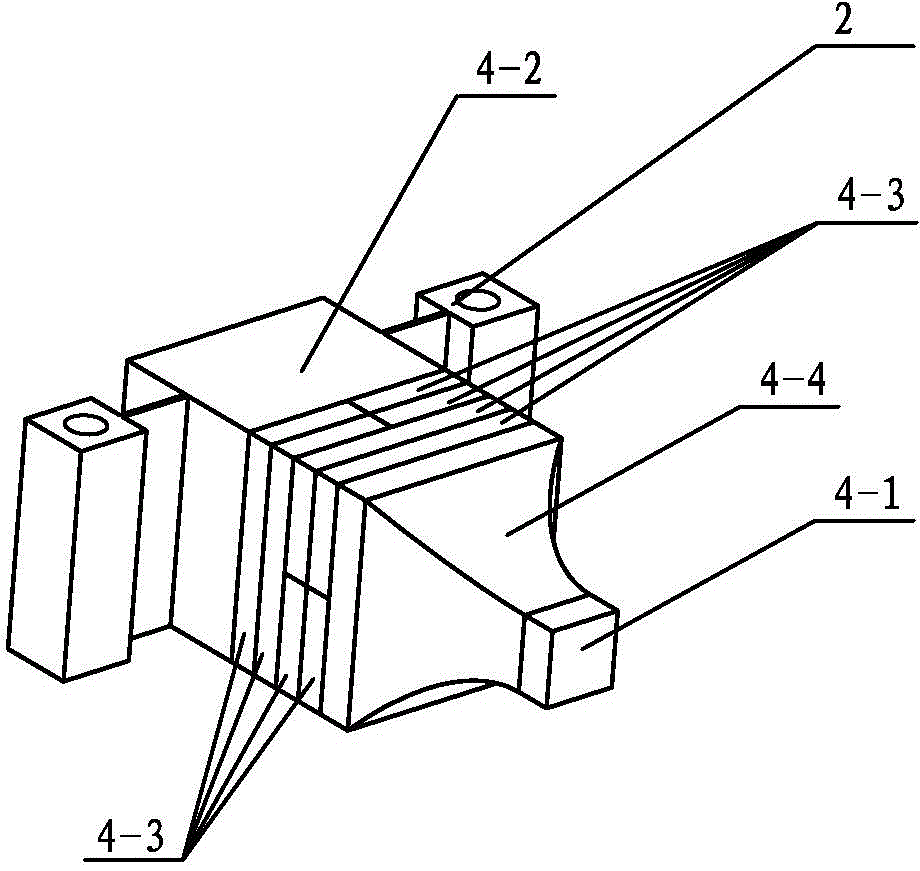
[0017] Specific embodiment three, combine Figure 1-Figure 3 This specific embodiment is described. The difference between this specific embodiment and the space expansion mechanism driven by the multi-piezoelectric vibrator stepping creep mode described in the first specific embodiment is that each piezoelectric vibrator 4 includes a metal base 4-2, A plurality of piezoelectric ceramic sheets 4-3, a horn 4-4 and a driving foot 4-1, the plurality of piezoelectric ceramic sheets 4-3 are sequentially stacked between the metal base 4-2 and the horn 4-4 Between, the side of the metal base 4-2 is fixedly connected with the mounting seat 2, the horn 4-4 is a block body whose cross-section gradually becomes thinner, and the large end of the horn 4-4 is connected to the piezoelectric ceramic sheet 4-3 , The small end of the horn 4-4 is provided with a driving foot 4-1, and the side of the driving foot 4-1 is connected with the outer surface of the driving shaft 5.


PUM


Abstract

The invention discloses a space deployment mechanism driven based on a multi-piezoelectric vibrator step crawling mode, which relates to the field of space deployment mechanisms and aims at solving the problems of complicated structure, serious electromagnetic interference and complicated self locking existing in the current electromagnetic motor driving-type space deployment mechanism. The space deployment mechanism driven based on the multi-piezoelectric vibrator step crawling mode comprises a base, two shaft extension sleeves, two deployment mechanisms, four piezoelectric vibrators, two driving shafts and a mounting seat, wherein two opposite side walls of the base are provided with through holes, and the through holes in the two side walls are coaxial; the two shaft extension sleeves are fixed in the two through holes; the two deployment mechanisms are fixed on the two opposite side walls of the base respectively; the four piezoelectric vibrators are fixed inside the base via the mounting seat; and one ends of the two driving shafts are tightly connected with two piezoelectric vibrators via a pretightening force, and the other ends pass through the shaft extension sleeves to be connected with the two deployment mechanisms respectively. Thus, relaxation and contraction of the space deployment mechanism can be realized.

Description

technical field [0001] The invention relates to the field of space deployment mechanisms, in particular to the field of space deployment mechanisms driven by multi-piezoelectric vibrator stepping and creeping modes. Background technique [0002] The space deployment mechanism is widely used in the fields of flexible solar cells, antennas, support structures for ground remote sensing and deep space probes, etc. The most basic function is to realize the simultaneous expansion and contraction of several space deployment mechanisms; the current mature space deployment mechanism The mechanism uses a rotating electromagnetic motor as the driving element. Since the output motion of the electromagnetic motor is rotating motion, the speed is high, and the output is small, it is generally necessary to cooperate with the reducer to achieve the purpose of deceleration and force increase, which makes the driving structure very complicated and the production cost is high; Since the electr...

Claims


Application Information

Patent Timeline
IPC IPC(8): H02N2/04
Inventor 刘英想王鼎汶陈维山刘军考
Owner HARBIN INST OF TECH
Why Eureka
Try Eureka