
Liquid crystal display device

A technology of liquid crystal display devices and liquid crystal display panels, applied in light guides, optics, instruments, etc., can solve the problems of reduced position accuracy, uneven light quantity, deviation, etc., and achieve the effect of simple internal structure

Inactive Publication Date: 2011-05-18
SHARP KK
View PDF1 Cites 3 Cited by
  • Summary
  • Abstract
  • Description
  • Claims
  • Application Information

AI Technical Summary

Problems solved by technology

[0005] and, whether in Figure 8 and Figure 11 In any of the cases shown, a backlash force is generated in the FPC board 116 that is bent due to being rolled up, and because of this, the position of the LED 131 with respect to the side surface (light receiving surface) 132S of the light guide plate 132 is easily changed from the desired position. The position deviation of (in a word, the position accuracy of LED 131 is easy to reduce)
[0006] In addition, the positional deviation of the LED (light source) 131 relative to the side surface 132S of the light guide plate 132 becomes a cause of uneven light quantity in the light from the backlight unit 139, and further, causes a decrease in the display quality of the liquid crystal display device 169. a reason

Method used


Image

  • Liquid crystal display device
  • Liquid crystal display device
  • Liquid crystal display device

Examples


Embodiment approach 1

[0040] If one embodiment is described with reference to the drawings, it will be as follows. In addition, for the sake of convenience, hatching, member reference numerals, etc. may be omitted, and in this case, refer to other drawings. In addition, black dots on the drawings represent directions perpendicular to the paper surface.

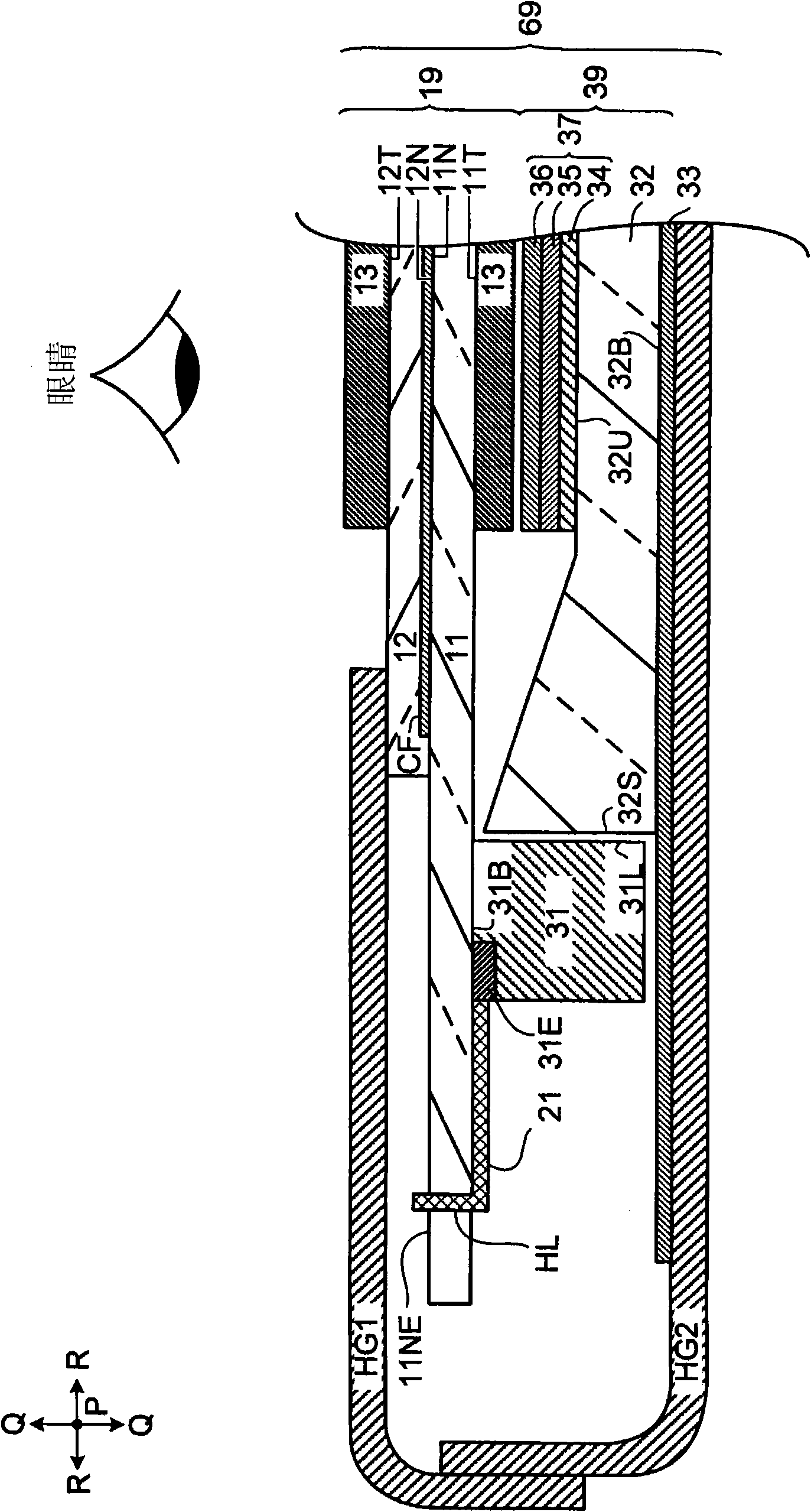
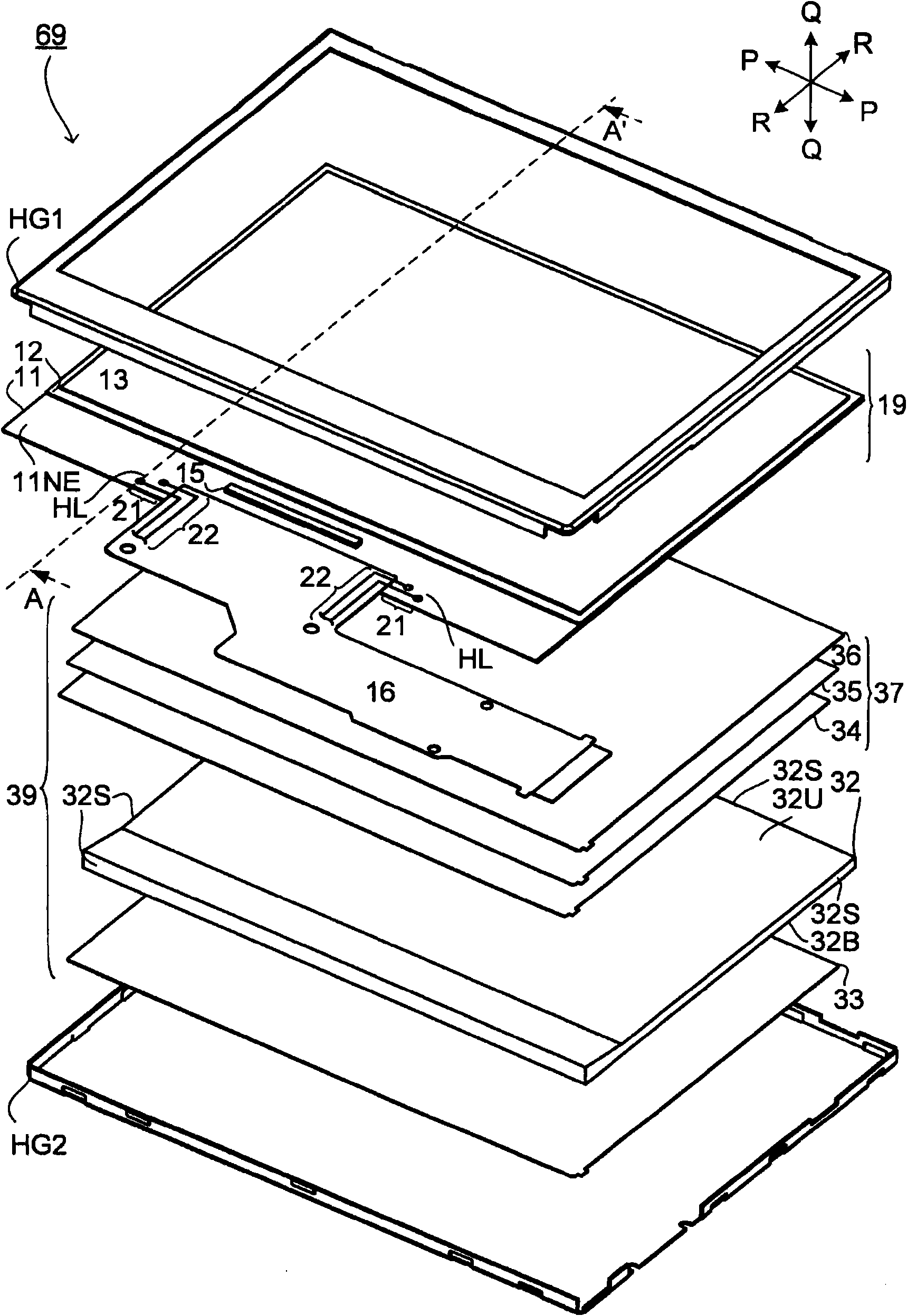
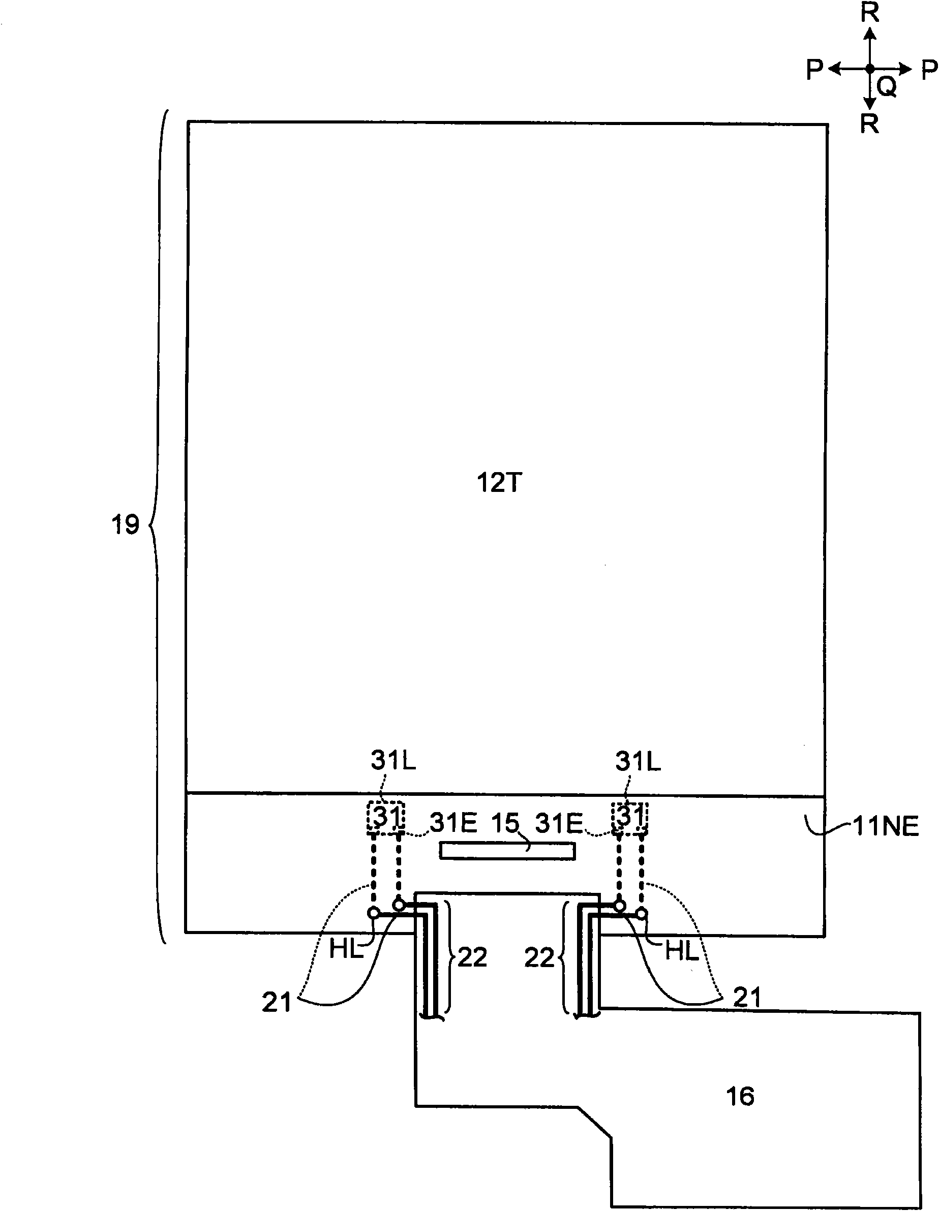
[0041] figure 2 is an exploded perspective view of the liquid crystal display device 69, image 3 Yes figure 2 A plan view of the liquid crystal display panel 19 and the like included in the illustrated liquid crystal display device 69 is shown. figure 1 Yes figure 2 A cross-sectional view of the liquid crystal display device 69 shown by the arrow line A-A'.

[0042] like figure 1 and figure 2 As shown, the liquid crystal display device 69 includes a liquid crystal display panel 19, a backlight unit 39, and a housing HG sandwiching them (in addition, the housing HG covering the liquid crystal display panel 19 is referred to as a front ...


PUM


Abstract

An LED (31) is mounted on an active matrix substrate (11), and a light-emitting surface (31L) of the LED (31) is on the outer substrate surface (11T) side of the active matrix substrate (11).

Description

technical field [0001] The present invention is a liquid crystal display device. Background technique [0002] Recently, thin display devices have gradually become mainstream. As an example of such a display device, there are Figure 8 ~ Figure 10 The liquid crystal display device 169 is shown. Figure 9 It is an exploded perspective view of the liquid crystal display device 169 . Figure 10 Yes Figure 9 A plan view of the liquid crystal display panel 119 and the like included in the illustrated liquid crystal display device 169, Figure 8 Yes Figure 9 A cross-sectional view of the illustrated liquid crystal display device 169 indicated by an arrow on line E-E'. [0003] like Figure 8 and Figure 9 As shown, the liquid crystal display device 169 includes a liquid crystal display panel 119 and a backlight unit 139 that irradiates light to the liquid crystal display panel 119 . and, if Figure 7 ~ Figure 9 As shown, the FPC (Flexible Printed Circuits: flexible prin...

Claims


Application Information

Patent Timeline
IPC IPC(8): G02F1/13357
CPCG02B6/009G02B6/002G02F2001/133567G02F1/133615G02B6/0083G02B6/0073G02F1/1362G02F1/133567
Inventor 梅川一郎
Owner SHARP KK
Learn More