Strip threading method of strip steel in silicon steel continuous annealing drying furnace

A drying furnace and silicon steel technology, applied in furnaces, heat treatment furnaces, furnace types, etc., can solve the problems of inconvenient threading, difficult operation, and affecting productivity, and achieve the effects of reducing the difficulty of threading, simple operation, and improving productivity

Inactive Publication Date: 2012-11-21
WISDRI WUHAN WIS IND FURNACE
View PDF0 Cites 0 Cited by
  • Summary
  • Abstract
  • Description
  • Claims
  • Application Information

AI Technical Summary

Problems solved by technology

[0006] 1. The length of the belt threading rod is generally at least 7-8m, which is often affected by the distance between the equipment before and after the drying furnace, which makes it inconvenient to wear the belt;
[0007] 2. Temporary furnace rollers (6 to 7 pieces) must be installed before each belt threading, and the temporary furnace rollers will be removed after the belt threading is completed, which is not only difficult to operate, but also affects productivity

Method used


Image

  • Strip threading method of strip steel in silicon steel continuous annealing drying furnace
  • Strip threading method of strip steel in silicon steel continuous annealing drying furnace
  • Strip threading method of strip steel in silicon steel continuous annealing drying furnace

Examples


Embodiment Construction

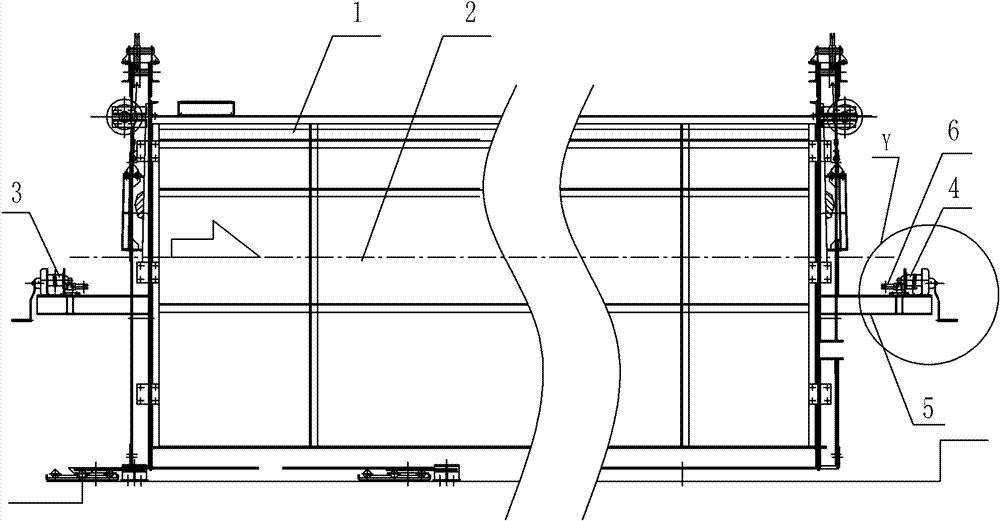
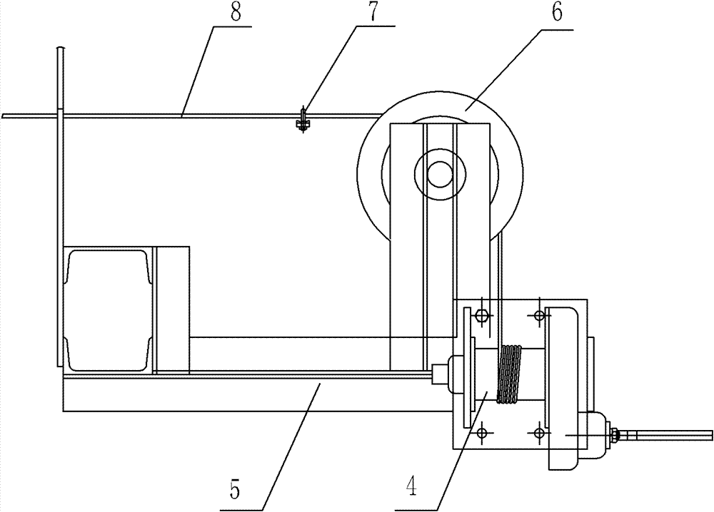
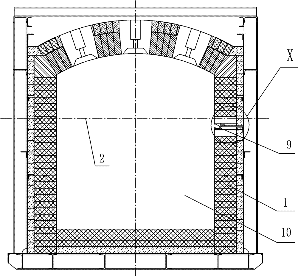
[0029] Such as figure 1 , figure 2 , image 3 , Figure 4 Shown, the belt threading method of strip steel in silicon steel continuous annealing drying furnace, it comprises the following steps:

[0030] 1) In the inner wall of the furnace wall of the silicon steel continuous annealing drying furnace, a heat-resistant steel groove part 9 is arranged along the moving direction of the strip steel. The distance between the center line of the heat-resistant steel groove part 9 and the strip steel passing line 2 is 0~ 500mm (that is, 0-500mm higher than the strip steel passing line, or 0-500mm lower than the strip steel passing line), the heat-resistant steel groove part 9 is provided with a concave groove along the moving direction of the strip steel; the silicon steel is continuously annealed and dried The entrance support frame is fixed on the furnace wall of the furnace entrance (that is, the entrance support frame is located at the entrance end of the furnace wall), and the...


PUM


Abstract

The invention relates to a strip threading method of strip steel in a silicon steel continuous annealing drying furnace, which is characterized by comprising the following steps: 1) arranging a heat-resistant steel groove piece along the movement direction of the strip steel on the inner side wall of the furnace wall of the silicon steel continuous annealing drying furnace, and penetrating a heat-resistant steel wire rope through the groove from the heat-resistant steel groove piece; and 2) threading a strip: at the inlet of the silicon steel continuous annealing drying furnace, tying one endof a common steel wire rope on the heat-resistant steel wire rope, tying the other end of the common steel wire rope on the end head of the strip steel, enabling an entrance winch to work, firstly drawing one end of the common steel wire rope from the inlet of the silicon steel continuous annealing drying furnace to the outlet of the silicon steel continuous annealing drying furnace through the entrance winch, then drawing out the strip steel from the silicon steel continuous annealing drying furnace through the common steel wire rope at the outlet of the silicon steel continuous annealing drying furnace, and welding the end head of the drawn strip steel with another section of strip steel, thereby completing the threading of the strip. The method is simple to operate, and is safe and reliable.

Description

technical field [0001] The invention relates to a method for threading strip steel in a continuous annealing and drying furnace for silicon steel. Background technique [0002] At present, the belt threading of the silicon steel continuous annealing drying furnace is realized by the following methods: [0003] The length of the drying furnace is more than 20 meters, and the cross-section is about 2.5m×2.8m. After the chemical coating on the surface of the steel strip, it is dried through the high-temperature drying furnace at a certain speed. There are several furnace rollers in the furnace to support the running of the strip steel. Before layer drying, the strip must not touch the furnace rolls but is suspended. [0004] The threading of the strip steel is realized by a threading rod. When starting production or re-threading due to a broken strip, the strip threading rod made of heat-resistant steel with a length of about 10m is first tied to a section of steel wire rope, ...

Claims


Application Information

Patent Timeline
Patent Type & Authority Patents(China)
IPC IPC(8): C21D9/56C21D1/26
Inventor 石祥龚彦兵周末
Owner WISDRI WUHAN WIS IND FURNACE
Why Eureka
Try Eureka